Poulan Pro Ignition Switch Wiring Diagram – Let’s start by looking at different types terminals found in an ignition switch. These terminals are for the Ignition button, Coil and Accessory. Once we know the purpose of each terminal, we can then identify the various components of the ignition wiring. Then, we will discuss the functions for the Ignition switch, as well as the Coil. The next step is to focus on the accessory terminals.
Terminals for the ignition switch
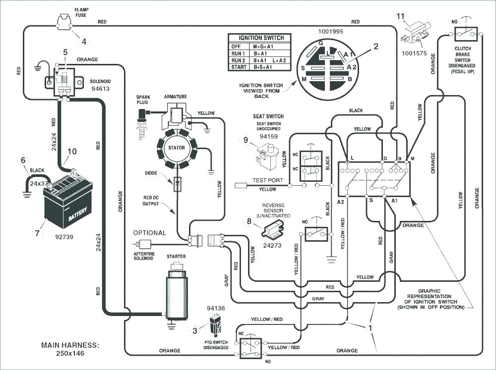
The ignition switch has three switches. They feed the battery’s voltage to different places. The first switch is used to drive the choke through pushing it, and another switch controls the ON/OFF setting. Different manufacturers use their own color-coding systems for the different conductors, that is described in a separate article. OMC uses this system. An additional connector is included in the ignition switch for attaching the tachometer.
Although most ignition switch terminals are duplicated, the numbers might not match the diagram. Verify the continuity of the wires first to ensure that they are correctly plugged in the ignition switch. This can be accomplished using a cheap multimeter. After you have verified the continuity of the wires you are able to install the connector. The wiring loom for an ignition switch that is supplied by the factory will be different from the one that you have in your car.
First, understand the differences between the ACC and the auxiliary outputs. The ACC/IGN terminals function as the default connection on the ignition switch. The START/IGN terminals are connected to the stereo or radio. The ignition switch’s function is for turning the car’s engine on and off. Older cars are identified by the initials “ACC”, “ST”, (for individual magneto cables) on their ignition switch terminals.
Coil terminals
The first step in determining the kind of ignition coil is to understand the terminology that is used. A basic diagram of the wiring will show you a number of terminals and connections. The coils have a specific operating voltage. The initial method of determining what type you’ve got is to check the voltage on S1, the main terminal. S1 should also be checked for resistance to determine if it’s a Type B, B, or an A coil.
The negative end of the chassis must be connected to connect to the coil’s lower-tension end. This is the ground in the diagram of the ignition wiring. The high tension part supplies positive directly the spark plugs. It is required to suppress the body of the coil’s metal be connected to its chassis, however, it is not necessary. The diagram of the ignition wiring will also reveal how to connect the negative and positive coil’s terminals. In some instances it is possible to find an ignition coil that is malfunctioning is identified by scanning at an auto parts store.
The black-and-white-striped wire from the harness goes to the negative terminal. The other white wire has a black color and goes to the terminal opposite. The contact breaker is linked to the black wire. It is possible to check the connections with a paperclip to take the wires out from the housing. Make sure you check that the terminals aren’t bent.
Accessory terminals
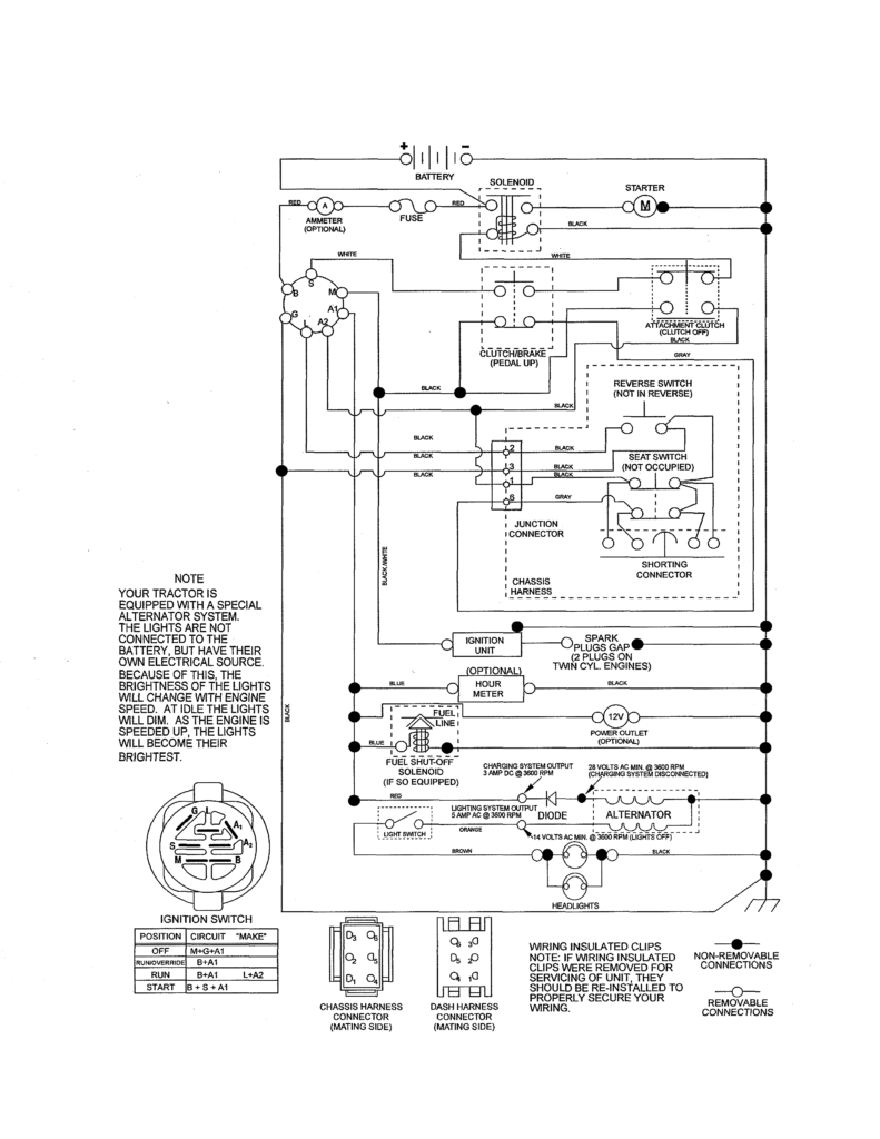
Diagrams of ignition wiring show the various wires used to power the car’s various components. Each part has four distinct color-coded connections. For accessories, red stands the starter solenoid’s color, yellow for battery, and blue for accessories. The “IGN” terminal is utilized to turn on the car, turn on the wipers, as well as other functions. The diagram shows how to connect the ACC and ST terminals to the other components.
The terminal BAT is where the battery is. Without the battery the electrical system will not get started. Additionally, the switch will not start without the battery. A wiring diagram can tell the location of your car’s battery. Your car’s accessory terminals connect to the ignition switch and the battery. The BAT terminal is connected to the battery.
Some ignition switches come with an additional position. It allows users to connect their outputs to another location without the ignition. Customers may want to utilize the auxiliary output in addition to the ignition. In order to use the additional output, wire the connector in the same colors as ignition, and connect it to the ACC terminal on the switch. While this is an excellent feature, there’s one thing to be aware of. Most ignition switches come with the ACC position when the car is in the ACC mode and a START mode when it is in IGN.
Gallery of Poulan Pro Ignition Switch Wiring Diagram
Gallery of Poulan Pro Ignition Switch Wiring Diagram


