1989 Ford F250 Ignition Wiring Diagram – We will first take a look at the different kinds of terminals that are used on the ignition switch. They are terminals that are used for Coil, Ignition Switch, and Accessory. Once we know what these terminals are, we will be able to identify the various parts of the ignition wiring. We’ll also discuss the functions and the Coil. Then, we’ll focus to the accessory terminals.
Terminals of ignition switch
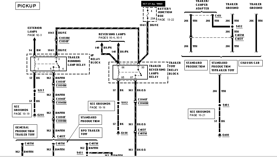
The ignition switch is comprised of three separate switches that feed the battery’s current to various locations. The first switch powers the choke. The second switch controls the ON/OFF of the ignition switch. Each manufacturer has their own color-coding system, which we will discuss in another article. OMC utilizes this method. Connectors can be attached to the ignition switch in order to add the digital Tachometer.
Although some ignition switch terminals may not be original, the numbering of each one might not match the diagram. First, check the continuity of each wire to ensure that they are properly connected to the ignition switches. This can be accomplished using an inexpensive multimeter. After you’re happy with the continuity of the wires, then you’ll be able to install the new connector. The wiring loom in a factory-supplied ignition system switch is distinct.
To connect the ACC outputs to the auxiliary outputs of your car, you need to understand how these two connections work. The ACC, IGN and START terminals are the default connections to the ignition switch. They also function as the primary connections to the radio and stereo. The ignition switch is the one that turns the engine of your car to and off. Older cars are identified by the alphabets “ACC”, “ST”, (for individual magneto cables) at their ignition switch’s terminals.
Terminals for coil
Understanding the terminology is the initial step to finding out what kind of ignition coil you’ve got. You’ll see a number of connections and terminals within the basic wiring diagram for ignition, including two primary, as well as two secondary. Each coil is operating at a certain voltage. The first step to determine which kind of coil you’re using is to examine the voltage at S1 or the primary terminal. To determine whether it’s an A, C or B coil you should also check the resistance of S1.
The chassis’ negative must be connected to the low-tension side. This is also the ground for the diagram of ignition wiring. The high tension part supplies positively directly to the spark plugs. The metal body of the coil needs to connect to the chassis to suppress the effect but is not electrically necessary. The wiring diagram for ignition will also show how to connect the positive coil’s terminals. In certain cases scanning your local auto parts store will be able to diagnose defective ignition coils.
The black-and-white-striped wire from the harness goes to the negative terminal. The white wire is black-colored and connects to the terminal opposite. The black wire is connected to the contact breaker. It is possible to check the connections with a pencil to take the wires out of the housing. It’s also crucial to make sure the terminals do not bend.
Accessory terminals
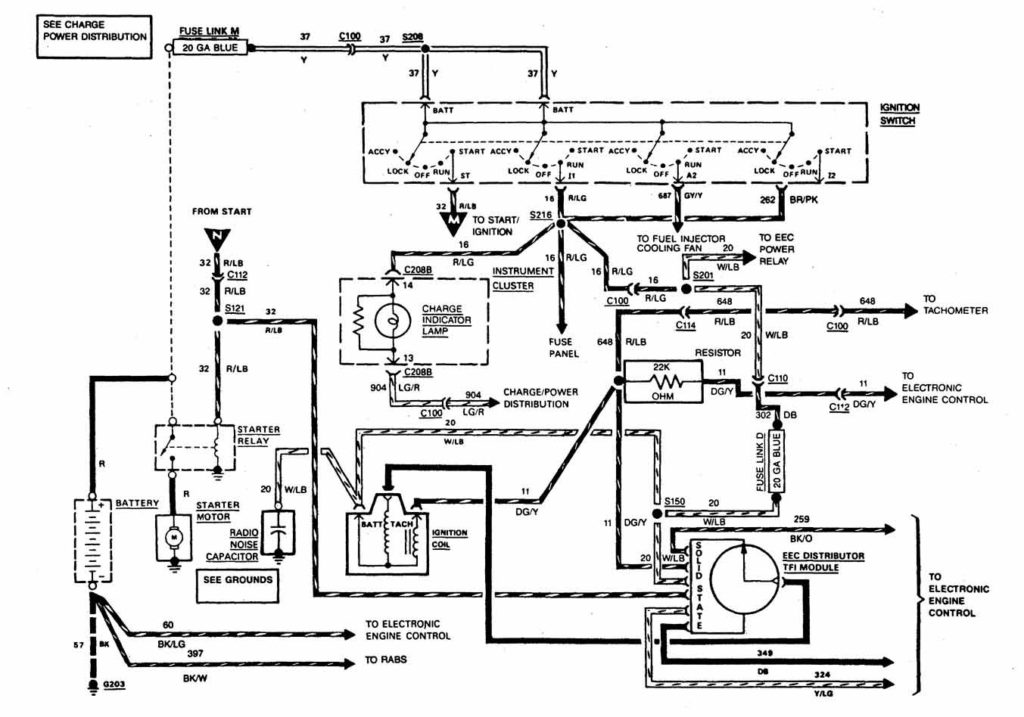
The wiring diagrams for the ignition show the different wires that provide power to the various parts of the car. In general there are four colors-coded terminals that are used for each component. To identify accessories, red stands the starter solenoid’s color, yellow is for battery and blue for accessory. The “IGN” terminal is used to start the car and operate the wipers as well as other operational functions. The diagram shows the connection to the ACCand ST terminals.
The terminal BAT connects the battery to the charger. The battery is necessary to allow the electrical system to begin. Additionally, the switch doesn’t turn on. You may refer to the wiring diagram if you are not sure where the batteries of your car are. The ignition switch as well as the battery are connected via accessory terminals. The BAT terminal is connected to the battery.
Certain ignition switches have an accessory position. This allows users to connect their outputs to a different place without having to turn on the ignition. Sometimes, users want to use an auxiliary output independent of the ignition. In order to use the additional output, wire the connector with the same colors as ignition, and connect it to the ACC terminal on the switch. Although this is a great option, there’s a thing you need to know. Most ignition switches are configured to be in an ACC position when the car is in the ACC position, whereas they’re set to the START position when the car is in the IGN position.
Gallery of 1989 Ford F250 Ignition Wiring Diagram
Gallery of 1989 Ford F250 Ignition Wiring Diagram


