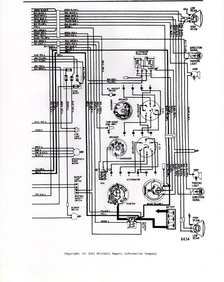
1967 Ford F100 Ignition Switch Wiring Diagram – In the beginning, we’ll take a look at the various kinds of terminals that are found in the ignition switch. These are the terminals that connect the Ignition, Coil, or Accessory. Once we have established what these types of terminals are for We will then discover the various components of the 1967 Ford F100 Ignition Switch Wiring Diagram. In addition, we will discuss the functions of the Ignition switch and Coil. After that we will move on to the Accessory Terminals.
Terminals of ignition switch
An ignition switch has three switches. They transmit the battery’s voltage to different places. The first switch provides power to the choke and the third switch toggles the on/off status of the ignition switch. Different manufacturers have different color-coding systems to identify different conductors. We’ll discuss this in another article. OMC utilizes this method. Connectors can be attached to the ignition switch in order to connect the digital tachometer.
While the majority of ignition switch terminals do not have the original design however, the numbers may not be in line with the diagram. To make sure that the wires are correctly connected to the ignition switch, you must verify their continuity. You can do this with a simple multimeter. When you’re satisfied that the wires are in good continuity and you are able to connect the new connector. If your car is equipped with an original factory-supplied ignition switch (or an electrical loom) The wiring loom may differ from that of the car.
Understanding how the ACC outputs are connected to the auxiliary outputs of your car is vital. The ACC terminals as well as the IGN terminals function as the standard connections for your ignition switch. The START and IGN connections are the main connections for radio and stereo. The ignition switch is the engine’s on/off button. The terminals of the ignition switch on older cars are labeled with the alphabets “ACC” and “ST” (for the individual magneto wires).
Terminals for coil
Understanding the terms is the initial step to knowing what type of ignition coil you own. An ignition wiring diagram will reveal a variety of terminals and connections which include two primary terminals and two secondary. The operating voltage of every coil is different. It is important to first test the voltage at the S1 (primary terminal). S1 should also be tested for resistance in order to identify if it’s an A, Type B, or A coil.
The coil’s low-tension side must be connected with the chassis positively. This is the ground of the wiring for ignition. The high-tension part connects the spark plugs to a positive. It is essential for suppression purposes that the metallic body of the coil is connected to the chassis, however it isn’t essential. The diagram for the ignition wiring will also demonstrate the connections between the positive and negative coil’s terminals. In certain instances scanning your local auto parts store will help identify defective ignition coils.
The black-and-white-striped wire from the harness goes to the negative terminal. The positive terminal also gets the white wire that is black in its trace. The contact breaker is attached to the black wire. To test the connections between the two wires, use a paperclip and remove them from the housing. It is also important to make sure that the terminals aren’t bent.
Accessory terminals
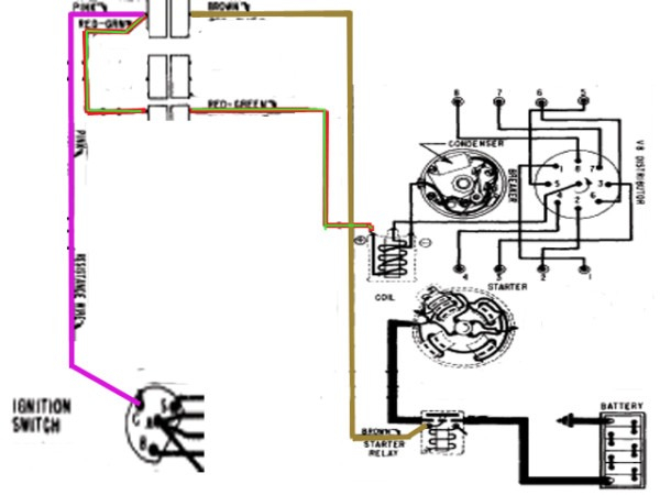
The wiring diagrams for the ignition show the different wires used to power the various components of the car. There are typically four colors of terminals connected to each part. The accessories are red while the battery is yellow, the starter solenoid green. The “IGN terminal” is used to provide power to the wipers as well as other operating features. The diagram illustrates how to connect ACC or ST terminals, and other.
The battery is connected to the terminal named BAT. The electrical system cannot begin without the battery. Additionally, the switch won’t begin to turn on. It is possible to refer to your wiring diagram if you’re unsure where your car’s batteries are. The accessory terminals of your vehicle are connected to the battery as well as the ignition button. The BAT Terminal is connected to the Battery.
Certain ignition switches have an additional position in which users can modify their outputs as well as control them without the need to use the ignition. Sometimes, customers want to utilize an additional output that is not connected to the ignition. For the auxiliary output to be used, wire the connector in the same shade as the ignition. Connect it to the ACC end of the switch. This feature is convenient however it does have one significant difference. Most ignition switches come with an ACC position when the car is in ACC mode and a START mode when the switch is in IGN.
Gallery of 1967 Ford F100 Ignition Switch Wiring Diagram
Gallery of 1967 Ford F100 Ignition Switch Wiring Diagram


