2008 Dodge Charger Ignition Wiring Diagram – First, let’s take a look at the different types of terminals used on the ignition switch. They include terminals for the Ignition switch, Coil, and Accessory. Once we know what these terminals are then we can identify the different parts in the ignition wiring. In addition, we will discuss the roles of the Ignition switch and Coil. Following that, we will move on to the Accessory Terminals.
Terminals for ignition switches

An ignition switch has three separate switches that feed the battery’s current to different destinations. The first switch powers the choke. The third switch regulates the ON/OFF of the ignition switch. Every manufacturer has its individual color-coding system that we’ll go over in a separate article. OMC follows this scheme. The connector allows for the attachment of a speedometer the ignition switch.
Even though some of the ignition switch terminals could not be authentic, the numbering of each may not be in line with the diagram. Check the continuity of all wires to ensure that they are properly plugged into the ignition switches. A multimeter is an excellent tool to check the continuity. Once you’re satisfied with the continuity, you can place the new connector. If you’re using a factory-supplied ignition switch, the wiring loom is different from the one you have in your car.
Before connecting the ACC outputs to the auxiliary outputs of your car, it is important to understand the basics of these connections. The ACC/IGN connections function as the default connections for the ignition switch. The START/IGN connections connect to the radio or stereo. The ignition switch is responsible for turning the car’s engine on and off. Older cars are equipped with ignition switch terminals labeled “ACC” or “ST” (for individual magnetowires).
Terminals for coil
The first step to determine the kind of ignition coil is to understand the terminology that is used. An ignition wiring diagram will reveal a variety of connections and terminals, which include two primary terminals and two secondaries. The operating voltage of each coil is different. Therefore, it is essential to first check the voltage at S1 (primary terminal). S1 must be checked for resistance to identify if the coil is type A, B and/or C.
The lower-tension side of the coil should be connected to the chassis”negative. This is also the ground in an ignition wiring diagram. The high-tension component provides the spark plugs with positive. The body of the coil has to be connected to the chassis to suppress the effect but is not electrically essential. There are also connections of the negative and positive coil’s terminals on the ignition wiring diagram. In some cases you’ll discover that the ignition coil is damaged and is easily identified with a scan at an auto parts shop.
The black-and-white-striped wire from the harness goes to the negative terminal. The positive terminal receives the other white wire, which has a trace of black. The black wire connects to the contactbreaker. If you’re not sure about the connections between both, you can use a paper clip to remove them from the plug housing. Be sure the terminals do not bend.
Accessory Terminals
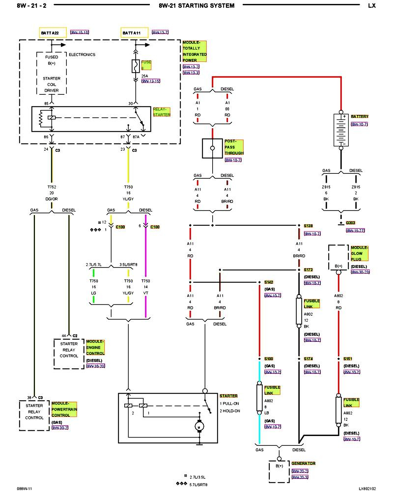
Diagrams of ignition wiring show the various wires that are used for powering the various components. There are generally four color-coded terminus for each component. The accessories are colored red and the battery yellow, and the starter solenoid green. The “IGN” terminal is used to start the vehicle, controlling the wipers, and for other functions. The diagram shows the connections between the ACC- and ST terminals.
The terminal BAT is the connection to the battery. Without the battery the electrical system will not get started. Furthermore, the switch won’t start. A wiring diagram can tell you where to find the battery in your car. The accessory terminals on your vehicle connect to the battery as well as the ignition switch. The BAT terminal is connected with the battery.
Some ignition switches come with an additional “accessory position” that lets users alter their outputs without the ignition. Customers may want to use the auxiliary output independently of the ignition. Make use of the auxiliary output by connecting the connector to an ACC terminal on your switch using the same colors. This feature is convenient, but it has one major differentiator. Most ignition switches will be in an ACC position when the vehicle is in ACC, but they’ll be in the START position if the car is in IGN.
Gallery of 2008 Dodge Charger Ignition Wiring Diagram

Gallery of 2008 Dodge Charger Ignition Wiring Diagram


