1967 Ford Mustang Ignition Coil Wiring Diagram – First, we will examine the different types of terminals on the ignition switch. These are terminals for the Ignition, Coil, or Accessory. Once we know what these kinds of terminals are We will then identify the different parts of the 1967 Ford Mustang Ignition Coil Wiring Diagram. We will also cover the different functions of the Ignition Switch and the Coil. Then, we’ll focus to the accessory terminals.
Terminals for ignition switches
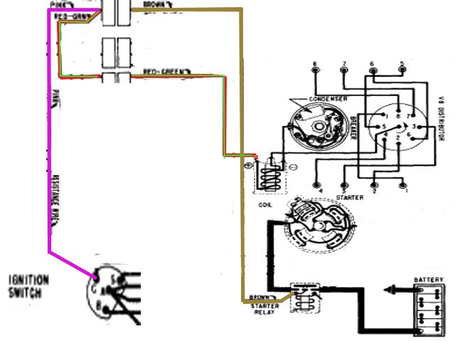
The ignition switch consists of three different switches. They are the ones that supply the battery’s power to several destinations. The first switch provides the choke with power when it is pushed. The second is the ignition switch’s ON/OFF position. Different manufacturers have distinct color-coding systems that correspond to the conductors. OMC employs this system. The adapter is attached to the ignition switch to allow for the addition of a Tachometer.
While some ignition switch terminals do not come in original form, the numbering may not match the diagram. Check the continuity of each wire to ensure they are correctly plugged into the ignition switches. You can do this with a simple multimeter. When you’re happy with the connection it’s time to connect the new connector. The wiring loom for an ignition switch that is supplied by the manufacturer will differ from the one you have in your car.
In order to connect the ACC outputs to the auxiliary outputs of your car, you’ll need to first understand the way these two connections function. The ACC/IGN connections function as the default connections for the ignition switch. The START/IGN terminals are connected to the radio or stereo. The ignition switch operates the engine’s off/on button. The terminals of older vehicles’ ignition switches are labeled with “ACC” as well as ST (for individual magneto wires).
Coil terminals
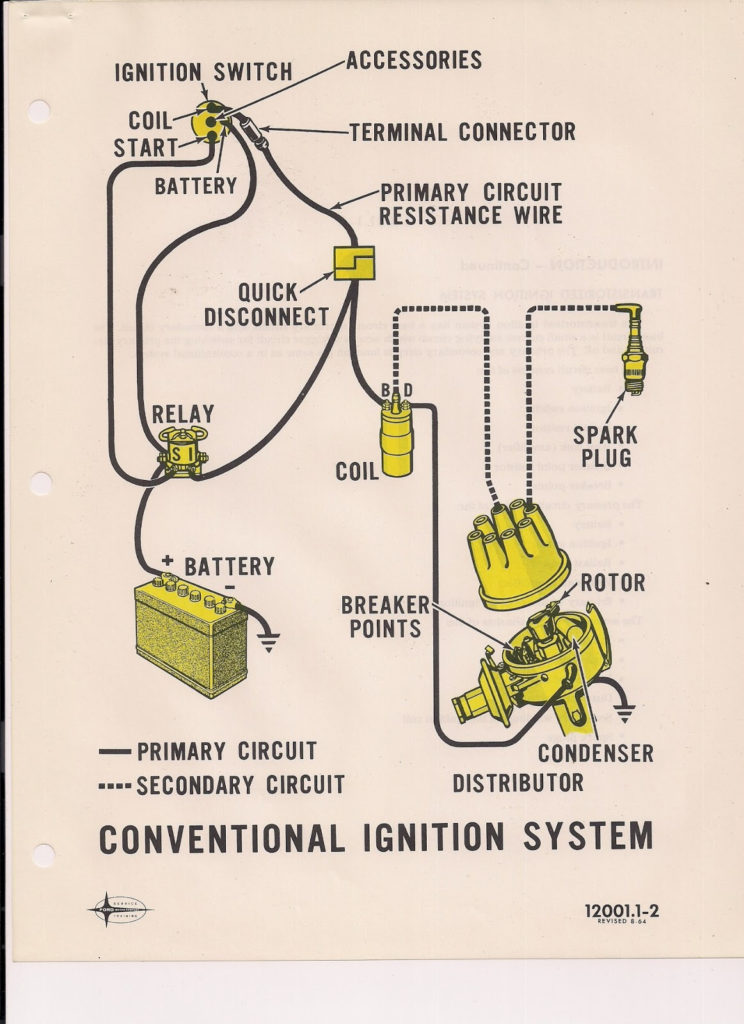
Understanding the terms used is the initial step towards finding out the right kind of ignition coil to choose. In a simple diagram of the wiring for ignition you’ll see a number of different connections and terminals, such as two primary and two secondary. You need to determine the type of coil that you are using by testing the voltage on the primary terminal, S1. S1 must also be subjected to resistance testing to determine if it is a Type A or B coil.
The chassis’ negative needs to be connected to the side of low-tension. This is what’s called the ground on the ignition wiring diagram. The high-tension side delivers positive direct to the spark plugs. The body of the coil has to be connected to the chassis to prevent it from being smothered, but it is not electrically required. The wiring diagram of the ignition will show you how to connect the terminals of the negative or positive coils. Sometimes, a defective ignition coil can be identified by a scan done at an auto parts shop.
The black-and-white-striped wire from the harness goes to the negative terminal. The terminal for the negative is served by the trace in black that’s attached to the white wire. The contact breaker is attached to the black wire. If you’re not certain about the connections between the two, try using the clip of a paperclip to remove them from the plug housing. Also, make sure to verify that the connections have not been bent.
Accessory terminals
Diagrams of ignition wiring show the wires used to provide power to various components of the vehicle. There are generally four color-coded terminus for each component. To identify accessories, red is for starter solenoid, yellow is for battery and blue for accessory. The “IGN” terminal is used to turn on the car, operate the wipers and other features. The diagram illustrates how you can connect ACC or ST terminals as well as the rest.
The battery is attached to the terminal called BAT. Without the battery, the electrical system does not begin. Additionally, the switch will not start without the battery. A wiring diagram can inform you where to find the battery of your car. The ignition switch as well as the battery are connected by the accessory terminals. The BAT Terminal is connected to the battery.
Some ignition switches come with an independent “accessory” position, in which users can control their outputs with no ignition. Sometimes, customers want to utilize the auxiliary output separately from the ignition. You can utilize the additional input by connecting the connector to the ACC terminal. Although this is a useful feature, there is one important difference. Some ignition switches are set to have an ACC location when the car has moved into the ACC position. They’ll also be in the START position once the vehicle is entered the IGN position.
Gallery of 1967 Ford Mustang Ignition Coil Wiring Diagram
Gallery of 1967 Ford Mustang Ignition Coil Wiring Diagram


