1967 Nova Ignition Switch Wiring Diagram – Let’s begin by looking at different types terminals found on the ignition switch. These terminals comprise the Ignition switch as well as the Coil along with the Accessory. After we’ve identified the purpose of these terminals, we can recognize the various parts of the ignition wiring. We’ll also go over what functions are available for the Ignition switch as well as the Coil. We will then discuss the roles of the Ignition switch and Coil.
The ignition switch’s terminals
The ignition switch has three switches. They supply the battery’s voltage to different locations. The ON/OFF setting of the ignition switch is controlled by the third switch, which delivers power to the choke when it’s pulled. Different manufacturers use different colors-coding systems to match the conductors. OMC uses this system. The ignition switch is also equipped with an option to connect a tachometer.
While most ignition switch terminals may not be original, the numbers for each might not be consistent with the diagram. Before plugging into the ignition switch be sure to test the continuity. A cheap multimeter can assist you in this. Once you are satisfied with the continuity of the wires you can connect the new connector. The wiring loom for an ignition switch that is supplied by the manufacturer will differ from the one that you have in your car.
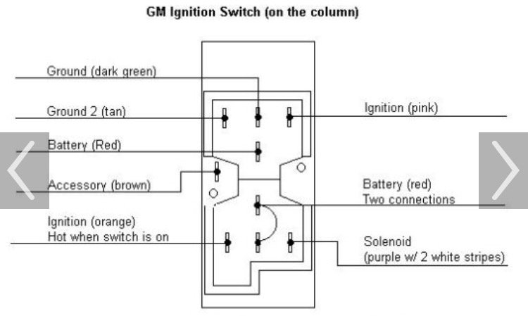
Understanding how ACC outputs connect to the other outputs inside your car is vital. The ACC, IGN and START terminals are the primary connections to the ignition switch. They also serve as the main connections to the radio and stereo. The ignition switch’s function is for turning the car’s engine on and off. The terminals of older vehicles’ ignition switches are labeled with “ACC” and ST (for individual magneto wires).
Terminals for coil
To identify the kind of ignition coil, the initial step is to understand the terminology. In a simple diagram of the wiring for ignition you’ll see several different connections and terminals, which include two primary and two secondary. You need to determine the kind of coil you are using by testing the voltage on the primary terminal, S1. S1 should be checked for resistance to determine if the coil is type A, B and/or C.
The lower-tension side of the coil should be connected to the chassis”negative. This is also the ground in the diagram of ignition wiring. The high-tension component supplies positively direct to the spark plugs. It is necessary for suppression purposes that the metallic body of the coil is connected to its chassis but not essential. You will also see the connections of the negative and positive coil terminals on the ignition wiring diagram. In some cases, you’ll find that a malfunctioned ignition coil is easily identified with a scan in an auto parts store.
The black-and-white-striped wire from the harness goes to the negative terminal. The terminal that is negative is served by the black trace joined to the white wire. The contact breaker is attached to the black wire. If you’re not certain about the connection between the two, try using a paper clip to remove them from the housing of the plug. Make sure that the connectors do not bend.
Accessory terminals
Ignition wiring diagrams depict the different wires used for powering the various components. Each component is equipped with four distinct connections that are color coded. The red symbol represents accessories, yellow for the battery, and green for the solenoid for starters. The “IGN terminal lets you start the car, control the wipers, and any other operation features. The diagram illustrates the connection between the ACCas well as ST terminals.
The terminal BAT connects the battery to the charger. The electrical system will not start without the battery. Furthermore, the switch doesn’t turn on. To find your car’s battery examine the wiring diagram. The accessory terminals in your car are connected to the ignition switch, as well as the battery. The BAT Terminal is connected to the battery.
Some ignition switches come with an accessory position. It allows users to connect their outputs to a different location without the ignition. Sometimes, customers would like the auxiliary output to be used separately from the ignition. To make use of the auxiliary output, connect the connector in the same colors as the ignition, and connect it to the ACC terminal on the switch. While this is an excellent feature, there’s one crucial distinction. Most ignition switches will be in an ACC position if the car is in the ACC however they will be in the START position if the car is in IGN.
Gallery of 1967 Nova Ignition Switch Wiring Diagram
Gallery of 1967 Nova Ignition Switch Wiring Diagram


