1982 Corvette Ignition Wiring Diagram – We will first look at the various types of terminals on the ignition switch. These terminals serve for the Ignition button, Coil and Accessory. Once we know the purpose of these terminals and what they do, we can then determine the various components in the ignition wiring. We’ll also go over the roles of the Ignition switch and the Coil. Then, we’ll turn our attention to the Accessory terminals.
Terminals for ignition switch
There are three separate switches on an ignition switch, which transmit the battery’s current voltage to several different locations. The ON/OFF position of the ignition switch is controlled by the first switch, which delivers power to the choke when it’s pushed. Each manufacturer has their own color-coding system, which we will discuss in another article. OMC follows this method. A tachometer adapter is installed on the ignition switch that allows the installation of a Tachometer.
While the majority of ignition switch terminals don’t have an original number, they may be equipped with a different number. To make sure that your wires are plugged in to the switch it is recommended to check their continuity. A cheap multimeter can aid in this. After you’ve confirmed that the wires are in good condition, you can then connect the connector. If your car has an ignition switch that is installed the wiring diagram may differ.
Understanding how the ACC outputs connect to the other outputs in your car is vital. The ACC and IGN terminals are the default connections for the ignition switch. the START and IGN terminals are the principal connections for stereo and radio. The ignition switch is responsible for turning the engine of your car on and off. The terminals on older cars’ ignition switches are labeled with “ACC” and ST (for specific magneto wires).
Terminals for Coil
The terms used to define the kind and model of an ignition coil is the primary thing. An ignition wiring diagram will display a range of terminals and connections comprising two primary and two secondary. Each coil is operating at a certain voltage. The first step to determine which kind you have is to check the voltage of S1 or the primary terminal. It is also recommended to test S1 for resistance in order to identify if it’s an A, B, or C coil.
The coil’s low-tension side is to be connected to the chassis’ positive. It is also the ground on the diagram of ignition wiring. The high-tension supply supplies positive directly to spark plugs. To prevent noise the coil’s body metal must be connected with the chassis. It’s not necessary for electrical use. The wiring diagram of the ignition will explain how to connect the terminals of either the positive or negative coils. In some cases scanning your local auto parts shop can help you identify defective ignition coils.
The black-and-white-striped wire from the harness goes to the negative terminal. The other white wire is black with a trace on it and it goes to the positive terminal. The black wire is connected to the contact breaker. To verify the wires’ connections, use a paperclip to remove them off the housing. It is also important to see that the terminals aren’t bent.
Accessory terminals
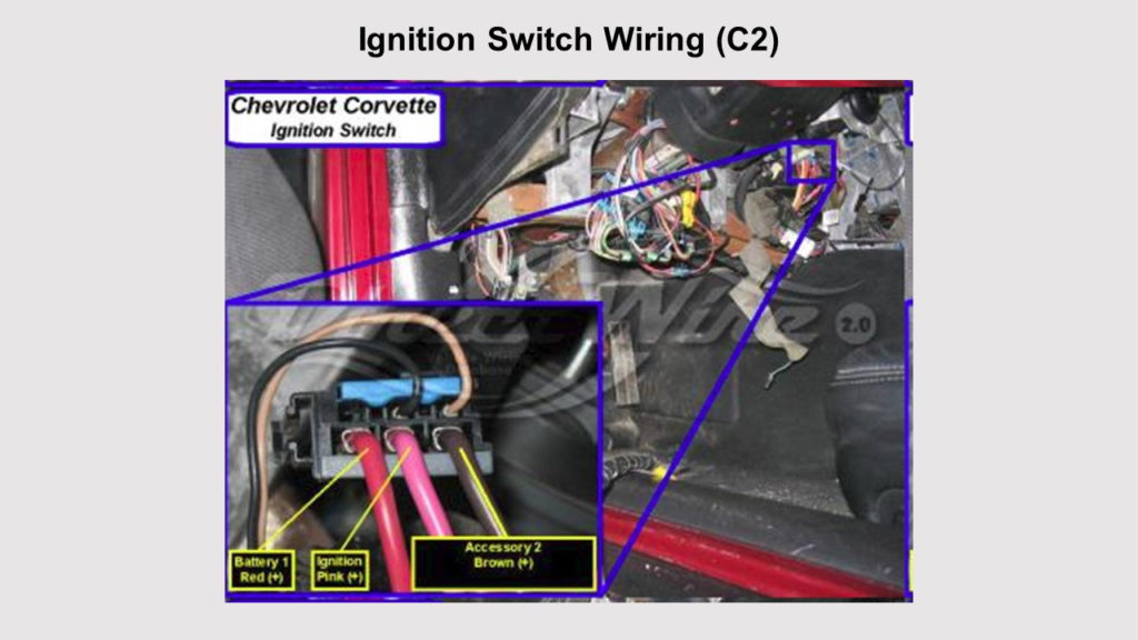
The ignition wiring diagrams show the different wires used to power the various components. There are generally four color-coded terminus for each component. The red color is for accessories, yellow the battery and green the starter solenoid. The “IGN” terminal is used to start the vehicle, controlling the wipers, and for other functions. This diagram shows how you can connect ACC and ST terminals with the rest of components.
The terminal BAT is where the battery is. The battery is vital to allow the electrical system to begin. In addition the switch isn’t turned on. If you’re not sure the location of your car’s battery situated, examine your wiring diagram to see the best way to find it. The accessory terminals of your car connect to the ignition switch as well as the battery. The BAT terminal connects to the battery.
Some ignition switches come with a separate “accessory” location, which allows users can control their outputs without the ignition. Customers sometimes want an auxiliary output that can be used independently from the ignition. Use the auxiliary output by connecting the connector to the ACC terminal on the switch that has the same color. This feature is convenient, but it has one significant distinction. The majority of ignition switches are configured to show an ACC status when the vehicle is at the ACC or START positions.
Gallery of 1982 Corvette Ignition Wiring Diagram
Gallery of 1982 Corvette Ignition Wiring Diagram


