1968 Camaro Ignition Wiring Diagram – First, we will examine the different types of terminals that are used on the ignition switch. These terminals are used for the Ignition button, Coil and Accessory. Once we have identified what these terminals do and what they do, we can then determine the various components in the ignition wiring. In addition, we will discuss the functions of the Ignition switch, as well as the Coil. The next step is to focus to the accessory terminals.
Ignition switch terminals
An ignition switch has three different switches that direct the battery’s current to different locations. The first switch provides power to the choke, while the second switch controls the ON/OFF status of the ignition switch. Different manufacturers use different color-coding systems that correspond to the conductors. OMC follows this system. This connector allows the attachment of a speedometer to the ignition switch.
Even though some of the ignition switch terminals could not be authentic, the numbering of each may not be in line with the diagram. You should first check the integrity of the wires to ensure that they are connected to the correct ignition switch. You can do this with an inexpensive multimeter. After you’re happy with the integrity of your wires, you will be able install the new connector. If your vehicle is equipped with an installed ignition switch the wiring diagram may differ.
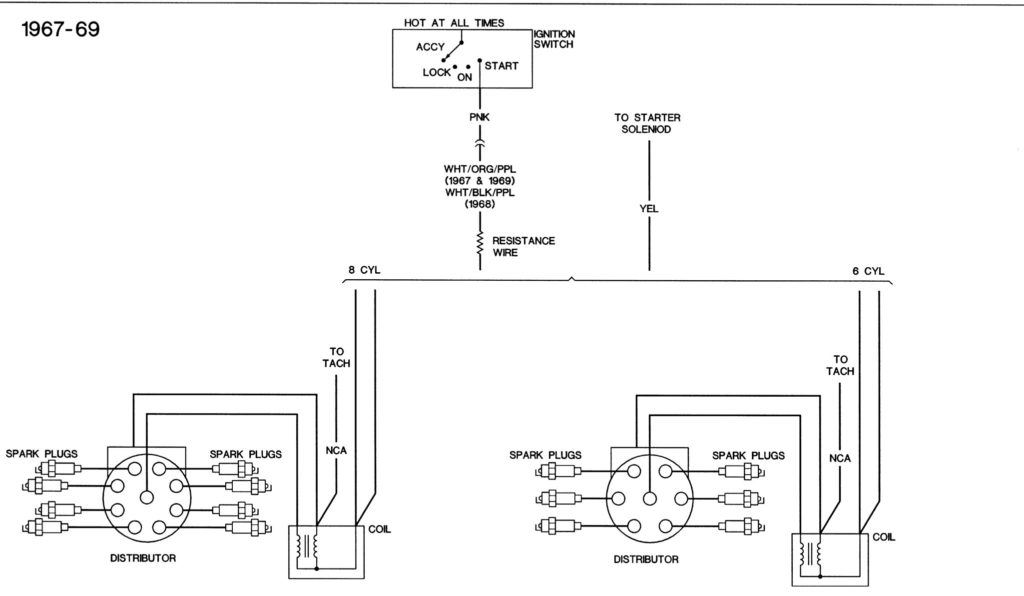
You must first understand the ways in which the ACC outputs and the auxiliary outputs function in order to connect them. The ACC terminals as well as the IGN terminals serve as the standard connections for your ignition switch. The START and IGN connections are the most important connections for stereo and radio. The ignition switch is the engine’s on/off button. The terminals for the ignition switch on older vehicles are marked with the initials “ACC” and “ST” (for individual magneto wires).
Coil terminals
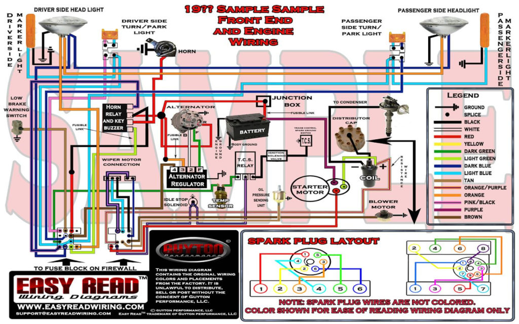
The first step to determine the kind of ignition coil is to comprehend the terms employed. An understanding of the basic wiring diagram for ignition will show you a number of connections and terminals. Each coil has an operating voltage. The first step in determining which kind of coil you have is to check the voltage at S1 or the primary terminal. It is also recommended to test S1 for resistance in order to determine if it’s a Type A or B coil.
The chassis’ negative should be connected to connect the coil’s low-tension end. This is also the ground for the diagram of ignition wiring. The high tension side provides positively directly to the spark plugs. To prevent noise, the coil’s metal body must be connected to chassis. But, it’s not required to connect electrically. The diagram of the ignition wiring will also show the connection of the positive coil’s terminals. Sometimes, a defective ignition coil can be identified with a scan at an auto parts shop.
The black-and-white-striped wire from the harness goes to the negative terminal. The white wire also has a black trace on it, and it connects to the positive terminal. The black wire connects to the contactbreaker. To verify the connections between the two wires use a paperclip and lift them from the housing. Make sure that the terminals do not bend.
Accessory terminals
Diagrams of ignition wiring depict the wires used in the power supply of the vehicle. There are generally four colored terminals that correspond to the component. The red symbol represents accessories, yellow represents the battery, and green for the starter solenoid. The “IGN terminal is used to start the car, operating the wipers and various other functions. This diagram shows how to connect ACC and ST terminals with the rest of components.
The terminal BAT connects the battery to the charger. The battery is necessary for the electrical system to get started. The switch won’t turn off if the battery isn’t present. You may refer to the wiring diagram if not sure where the batteries of your car are. The ignition switch and the battery are connected via accessory terminals. The BAT terminal is connected to the battery.
Some ignition switches offer an additional “accessory position” that allows users to adjust their outputs independently of the ignition. Customers may want to utilize the auxiliary output independently of the ignition. It is possible to use the additional input by connecting the connector to the ACC terminal. This is a useful feature, but there is an important distinction. Most ignition switches are designed to show an ACC status when the car’s at either the ACC or START position.
Gallery of 1968 Camaro Ignition Wiring Diagram
Gallery of 1968 Camaro Ignition Wiring Diagram


