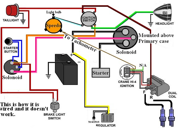
Ignition Wiring Simple Shovelhead Wiring Diagram – First, let’s take a look at the different types of terminals on the ignition switch. The terminals are the Ignition switch and Coil and the Accessory. Once we know the purpose of each type of terminal, it is possible to identify the parts of the ignition wiring. We will also discuss the roles of the Ignition switch and Coil. The next step is to focus on the accessory terminals.
Ignition switch terminals
An ignition switch is comprised of three switches. They supply the battery’s voltage to different locations. The first switch is the one that supplies the choke with power, and the third switch toggles the on/off status of the ignition switch. Every manufacturer has its own color-coding system, which we will discuss in another article. OMC follows the same system. The ignition switch is also equipped with a connector for adding the timer.
While the majority of ignition switch terminals do not have an original number, they may have a different one. You should first check the continuity of the wires to determine if they’re plugged into the ignition switch correctly. You can check this using a simple multimeter. Once you’ve verified the integrity of the wires you can then connect the connector. If your vehicle has an original factory-supplied ignition switch (or an electrical loom), the wiring loom will differ from the one in your car.
You must first understand the way that ACC outputs and the auxiliary outputs work in order to join them. The ACC and IGN terminals are the default connections for your ignition switch. the START and IGN terminals are the main connections to the radio and stereo. The ignition switch is the engine’s switch to turn off or on. Older cars are identified with the alphabets “ACC”, “ST”, (for individual magneto cables) at the ignition switch terminals.
Terminals for coil
Understanding the terms is the first step in knowing what type of ignition coil you’ve got. In a typical diagram of the wiring for ignition you’ll see various terminals and connections, including two primary and two secondary. Each coil is equipped with a distinct operating voltage. To determine which type of coil you’ve got, the first step is to test the voltage at S1, the primary terminal. S1 must be tested for resistance in order to determine if the coil belongs to type A, B or C.
The chassis’ negative end should be connected to connect the coil’s low-tension side. This is what you see in the diagram of wiring. The high-tension side supplies the positive power directly to the spark plugs. To prevent noise the coil’s body metal is required to be connected to the chassis. It’s not necessary for electrical use. The wiring diagram for the ignition will explain how to connect the terminals of either the positive or negative coils. In some instances, you’ll find that the ignition coil is damaged and can be diagnosed with a scan in an auto parts store.
The black-and-white-striped wire from the harness goes to the negative terminal. The terminal for the negative is served by the black trace joined to the white wire. The contact breaker is connected to the black wire. If you’re not sure about the connection between the two, try using an old paper clip to take them from the housing of the plug. Also, make sure to check that the terminals have not been bent.
Accessory terminals
Diagrams of ignition wiring show the wires that provide power to various components of the car. There are generally four colored terminals for each component. The red symbol represents accessories, yellow is for the battery and green is for the solenoid for starters. The “IGN” terminal lets you start the car, manage the wipers, or any other features that operate. The diagram shows how to connect the ACC and ST terminals to the rest of the components.
The battery is attached to the terminal called BAT. The electrical system will not start without the battery. A dead battery could make the switch not come on. A wiring diagram can inform you the location of your car’s battery. The accessory terminals of your car connect to the ignition switch as well as the battery. The BAT Terminal is connected to the battery.
Some ignition switches offer an additional “accessory position” that allows users to adjust their outputs independently of the ignition. Some customers want an auxiliary output that can be operated independently of the ignition. For the auxiliary output to be used, connect the connector in the same color as the ignition. Connect it to the ACC end of the switch. This is a great feature, but there is one important distinction. Many ignition switches have the ACC position when your vehicle is in ACC mode and a START position when the switch is in IGN.
Gallery of Ignition Wiring Simple Shovelhead Wiring Diagram
Gallery of Ignition Wiring Simple Shovelhead Wiring Diagram


