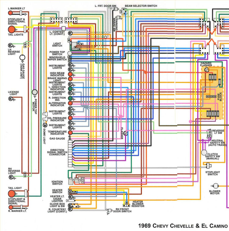
1969 Chevelle Ignition Switch Wiring Diagram – We will first examine the different types of terminals for the ignition switch. These are terminals for the Ignition, Coil, or Accessory. After we’ve established what these types of terminals are used for then we can identify the different parts of the 1969 Chevelle Ignition Switch Wiring Diagram. We’ll also discuss the functions of both the Ignition Switch and the Coil. Following that, we will proceed to the Accessory Terminals.
Terminals of ignition switch
There are three switches on an ignition switch, which provide the battery’s voltage to a variety of destinations. The first switch powers the choke. The second switch is responsible for the ON/OFF of the ignition switch. Different manufacturers use their own color-coding systems for the various conductors, which is documented in another article. OMC uses this method. A tachometer adapter is installed on the ignition switch, allowing for the addition of the tachometer.
Although the majority of ignition switch terminals can be duplicated, the numbers might not match the diagram. Check the integrity of the wires to determine if they’re connected to the correct ignition switch. A multimeter that is inexpensive can aid in this. After you’ve confirmed the integrity of the wires you can connect the connector. The wiring loom for an ignition switch that is supplied by the manufacturer will differ from the one in your vehicle.
Before you can connect the ACC outputs to your car’s auxiliary outputs it is crucial to be familiar with the fundamentals of these connections. The ACC terminals and IGN terminals serve as the standard connections for your ignition switch. The START and IGN connections are the primary connections for radio and stereo. The ignition switch is the engine’s off/on button. The terminals of the ignition switch on older vehicles are marked with the letters “ACC” as well as “ST” (for the individual magneto wires).
Terminals for coil
Understanding the terminology is the initial step in knowing what type of ignition coil you’ve got. An ignition wiring diagram will show a variety of connections and terminals, which include two primary terminals and two secondary. Each coil is equipped with a distinct operating voltage. To determine which type of coil you own, the first step is to check the voltage at the S1 primary terminal. You should also check S1 for resistance in order to determine whether it is a Type A or B coil.
The low-tension coil side must be connected at the chassis’s plus. This is the ground in the diagram of the ignition wiring. The high tension part supplies positive directly the spark plugs. For suppression purposes, the coil’s metal body must be connected to the chassis. But, it’s not necessary to electrically connect. The diagram for the ignition wiring will also demonstrate how to connect the positive and negative coil’s terminals. You may find an issue with the ignition coil which can be identified by scanning it at an auto parts retailer.
The black-and-white-striped wire from the harness goes to the negative terminal. Positive terminal receives a white wire that includes a black trace. The black wire is connected to the contact breaker. To check the connections, employ a paperclip, or a pencil to pull them out from the plug housing. You should also check to ensure that the terminals aren’t bent.
Accessory Terminals
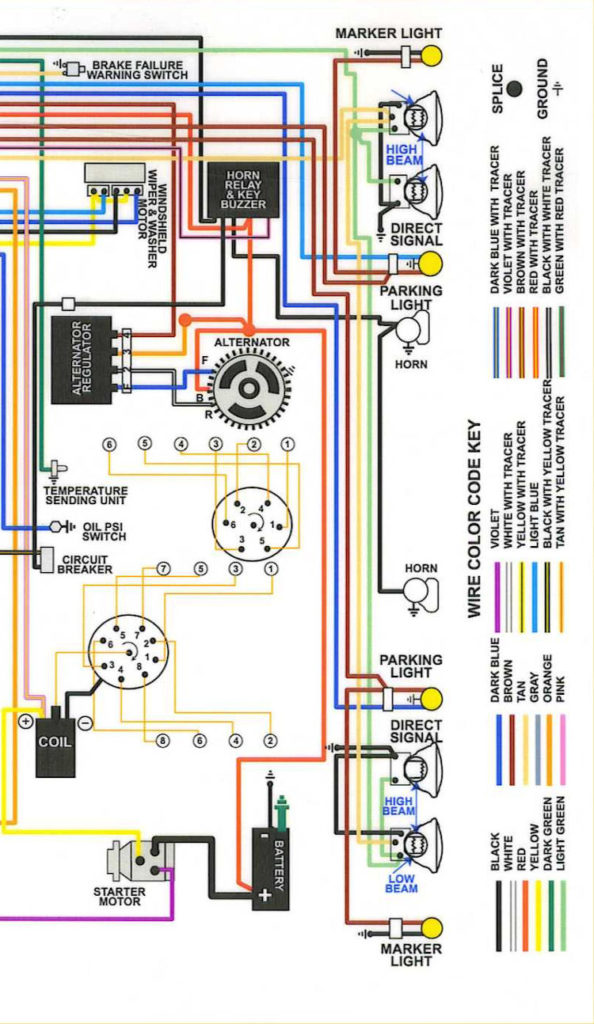
Ignition wiring diagrams show the different wires that are used to power the car’s various parts. There are typically four different colors-coded terminus of each part. Red is for accessories, yellow is for the battery, and green is the starter solenoid. The “IGN terminal” is used to provide power to the wipers and other operating functions. This diagram demonstrates how to connect ACC and ST terminals to the other components.
The terminal BAT is the connection to the battery. The electrical system will not start in the event that the battery isn’t connected. Additionally, the switch won’t start. It is possible to look up your wiring diagram to figure out where the batteries of your car are situated. The ignition switch is connected to the car’s battery. The BAT terminal connects to the battery.
Some ignition switches offer the option of an “accessory position” that allows users to alter their outputs without the ignition. Users may wish to use the auxiliary output in addition to the ignition. Make use of the auxiliary output by connecting the connector to the ACC terminal on the switch with the same colors. This is a useful option, but there’s one important difference. Some ignition switches are programmed to have an ACC position once the car has been moved into the ACC position. They’ll also be in START mode after the vehicle has been entered the IGN position.
Gallery of 1969 Chevelle Ignition Switch Wiring Diagram
Gallery of 1969 Chevelle Ignition Switch Wiring Diagram


