110cc Atv Ignition Wiring Diagram – Let’s begin by examining the different types and purposes of the terminals that are found in the ignition switches. These are the terminals for the Ignition, Coil, or Accessory. After we’ve identified what these terminals are then we can determine the various components in the ignition wiring. In addition, we will discuss the functions of both the Ignition Switch and the Coil. After that, we’ll turn our attention to Accessory terminals.
The terminals are for ignition switches.
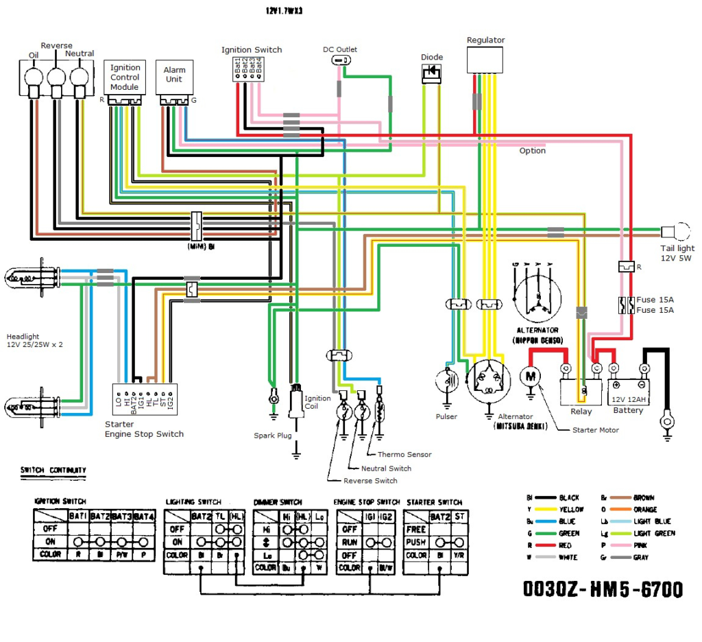
The ignition switch consists of three different switches. They are responsible for feeding the battery’s power to various destinations. The ON/OFF setting of the switch that controls the ignition is managed by the second switch, which provides the choke with power when it’s pushed. Different manufacturers have different colors-coding systems to match the conductors. OMC utilizes this method. The ignition switch also includes an adapter for the addition of a Tachometer.
Even though some ignition switch terminals don’t come in original form The numbering might not be in line with the diagram. To make sure that the wires are plugged in to the ignition switch it is recommended to check their continuity. A simple multimeter will aid in this. After you’re satisfied with the connection it’s time to connect the new connector. If your car is equipped with an original factory-supplied ignition switch (or wiring loom) The wiring loom might differ from that in your car.
It is essential to know the ways in which the ACC outputs and the auxiliary outputs function in order to join them. The ACC, IGN and START terminals are the default connections to the ignition switch. They also serve as the primary connections to your radio and stereo. The ignition switch turns the engine of your car ON and OFF. Older vehicles are identified with the initials “ACC”, “ST”, (for individual magneto cables) at their ignition switch’s terminals.
Terminals for coil
The language used to decide the type and model of the ignition coil is the primary thing. In a typical ignition wiring diagram you’ll see a number of different connections and terminals, which include two primary and two secondary. Each coil has a specific operating voltage. To determine what kind of coil you own first, you need to test the voltage at S1, which is the primary terminal. S1 must also be subjected to resistance tests to determine if it are an A or B coil.
The chassis’ negative needs to be connected to the side of low-tension. This is exactly what you can find in the wiring diagram. The high-tension side delivers the positive power direct to the spark plugs. The body of the coil has to connect to the chassis for suppression purposes however it isn’t electrically essential. You will also see the connections between the negative and positive coil’s terminals on the diagram of the ignition wiring. You may find an ignition coil problem that is easily identified by scanning it at an auto parts retailer.
The black-and-white-striped wire from the harness goes to the negative terminal. The positive terminal receives the white wire with a black trace. The contact breaker is linked to the black wire. It is possible to check the connections with a pencil to take the wires out of the housing. You should also check to ensure that the terminals aren’t bent.
Accessory terminals
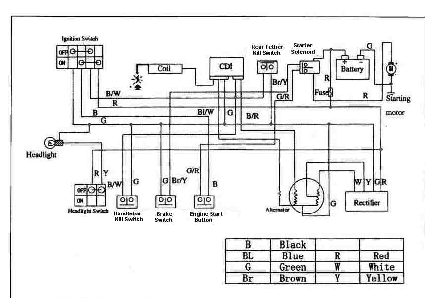
Diagrams of ignition wiring show the various wires that are used to power different components. There are generally four color-coded terminals that correspond to each component. The accessories are colored red and the battery yellow, and the starter solenoid is green. The “IGN” terminal can be utilized to turn on the car, control the wipers, as well as other features. The below diagram shows how to connect the ACC terminal as well as the ST terminals to other components.
The terminal called BAT is where the battery is connected. The electrical system won’t start without the battery. Furthermore, the switch won’t begin to turn on. A wiring diagram can tell the location of your car’s battery. The accessory terminals in your car connect to the ignition switch as well as the battery. The BAT terminal connects to the battery.
Some ignition switches offer an additional “accessory position” which allows users to alter their outputs without the ignition. Sometimes, customers would like the output of the auxiliary to be used independently from the ignition. You can use the secondary output by connecting it to an ACC terminal on your switch using the same colors. Although this is a great option, there’s a thing to be aware of. A lot of ignition switches can be configured to be in an ACC location when the car has been moved into the ACC position. They also will be in START mode when the vehicle has moved into the IGN position.
Gallery of 110cc Atv Ignition Wiring Diagram
Gallery of 110cc Atv Ignition Wiring Diagram


