Wiring Diagram Of Ignition Switch – The first step is to take a look at the different types of terminals on the ignition switch. These are terminals for the Ignition, Coil, or Accessory. After we’ve established what these kinds of terminals are for then we can determine the various parts of the Wiring Diagram Of Ignition Switch. In addition, we will discuss the functions of both the Ignition Switch and Coil. Then, we will concentrate on the accessory terminals.
Terminals of ignition switch
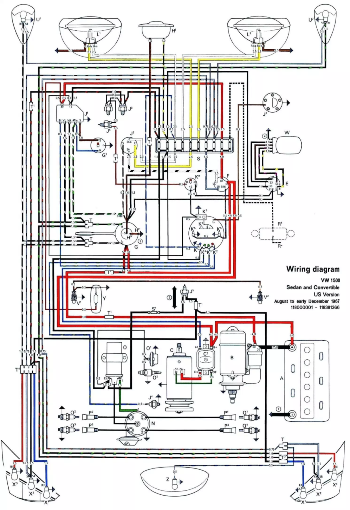
The ignition switch consists of three different switches. These are responsible for supplying the battery’s power to various locations. The first one is used to turn on the choke through pushing it, and another switch controls the ON/OFF position. Different manufacturers have different colors-coding systems to match the conductors. OMC uses this method. Connectors can be connected to the ignition switch in order to include the digital tachometer.
Although many ignition switch terminals don’t appear in their original configuration The numbering might not match the diagram. To make sure that your wires are correctly plugged in to the ignition switch, you must verify their continuity. This can be checked using a simple multimeter. After you have verified that the wires are in good condition, you can then connect the connector. The wiring loom used in an ignition system switch that is supplied by the manufacturer is distinct.
Knowing how the ACC outputs are connected to the other outputs inside your vehicle is crucial. The ACC and IGN terminals are the default connections for your ignition switch. the START and IGN terminals are the principal connections for the radio and stereo. The ignition switch is responsible for turning the car’s engine to and off. The terminals on older cars ignition switches are marked with “ACC” as well as ST (for the individual magneto wires).
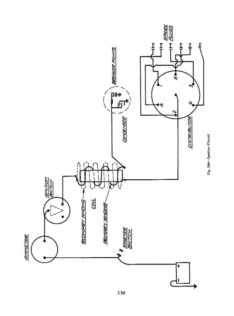
Terminals for coil
The terminology used to determine the kind and model of an ignition coil is the primary thing. In a simple diagram of the wiring for ignition there are several different terminals and connections, including two primary and two secondary. You need to determine the kind of coil you own by examining the voltage at the primary terminal, called S1. S1 must be checked for resistance to identify if the coil belongs to type A, B and/or C.
The low-tension end of the coil needs to be connected to the chassis’ negative. This is what you see in the diagram of wiring. The high-tension side provides the spark plugs with positive. To prevent noise the coil’s body metal is required to be connected to the chassis. It is not required to use electricity. You will also see the connections of the negative and positive coil’s terminals on the diagram of the ignition wiring. There could be an issue with the ignition coil that is easily identified by looking it up at an auto parts retailer.
The black-and-white-striped wire from the harness goes to the negative terminal. The positive terminal also receives a white wire that has a black trace. The black wire goes to the contact breaker. It is possible to check the connections using a paperclip to pull the wires out from the housing. It’s also crucial to make sure the terminals do not bend.
Accessory Terminals
The ignition wiring diagrams illustrate the different wires that provide power to the various parts of the car. There are generally four colors-coded terminus of each part. For accessories, red is for starter solenoid, yellow for battery, and blue is for accessory. The “IGN” terminal is used to start the car, operate the wipers and other features. The diagram illustrates how to connect ACC or ST terminals as well as the rest.
The terminal called BAT is the place where the battery is. The electrical system won’t start in the event that the battery isn’t connected. A dead battery can cause the switch to not come on. To find your car’s battery, check your wiring diagram. The ignition switch is connected to the battery of your car. The BAT Terminal is connected to the battery.
Certain ignition switches come with an additional position in which users can adjust their outputs and control them without having to turn on the ignition. Sometimes, a customer wants to use the auxiliary output separately from the ignition. For the auxiliary output to be used, connect the connector with the same shade as that of the ignition. Connect it to the ACC end of the switch. This is a convenient feature however it does have one major distinction. Most ignition switches will have an ACC position when the vehicle is in ACC, but they’ll be at the START position if the car is in IGN.
Gallery of Wiring Diagram Of Ignition Switch
Gallery of Wiring Diagram Of Ignition Switch


