1969 Gto Ignition Switch Wiring Diagram – First, we will look at the various types of terminals that are used on the ignition switch. These terminals comprise the Ignition switch, the Coil along with the Accessory. After we’ve identified what these terminals are and what they do, we can then be able to identify the various parts of the ignition wiring. We’ll also go over the roles of the Ignition switch and the Coil. Then, we will turn our attention towards the accessories terminals.
Terminals for ignition switches
An ignition switch is comprised of three switches. They supply the battery’s voltage to many different places. The choke is powered by the first switch. The third switch regulates the ON/OFF function of the ignition switch. Different manufacturers use their own color-coding systems for the various conductors, that is described in a separate article. OMC employs this system. The adapter is attached to the ignition switch that allows the installation of an tachometer.
Even though the majority of ignition switch terminals do not come in original form The numbering might not match the diagram. To ensure that your wires are properly connected to the ignition switch, you must verify their continuity. A multimeter is a good tool to check the continuity. Once you’ve verified the integrity of the wires you can then install the connector. If your car has an ignition switch installed the wiring diagram may differ.
It is important to know the differences between ACC and secondary outputs. The ACC and IGN connectors are the standard connections of the ignition switch. While the START, IGN, and ACC terminals are the main connections for radios or stereo, the START/IGN connections are the most important ones. The ignition switch acts as the engine’s off/on button. The terminals of the ignition switch on older vehicles are marked with the initials “ACC” as well as “ST” (for individual magneto wires).
Terminals for coil
Understanding the terms utilized is the initial step towards finding out the right kind of ignition coil you need. An ignition wiring diagram will show a variety of terminals and connections comprising two primary and two secondaries. The operating voltage of each coil is different. Therefore, it is crucial to test the voltage at the S1 (primary terminal). S1 should also be checked for resistance in order to identify whether it’s a Type B, B, or A coil.
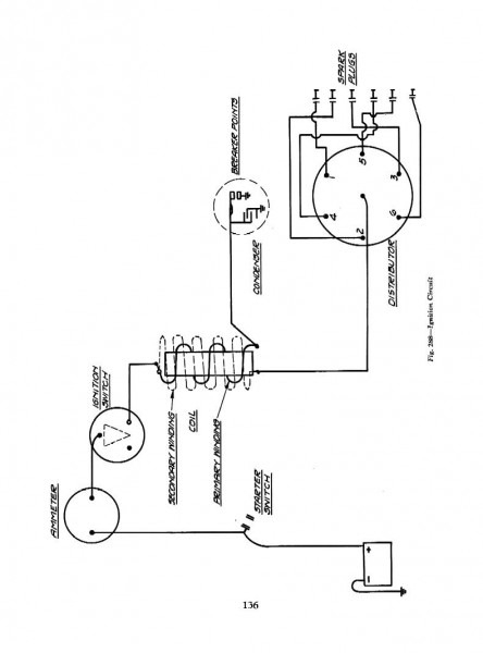
The coil’s low-tension side should be connected at the chassis’s plus. This is exactly what you can see in the diagram of wiring. The high-tension part provides positive direct to the sparkplugs. For suppression purposes the coil’s metal body must be connected to the chassis. It’s not necessary to use electricity. There are also connections between the positive and the negative coil’s terminals on the ignition wiring diagram. It is possible to find an ignition coil problem which can be identified by looking it up at an auto parts store.
The black-and-white-striped wire from the harness goes to the negative terminal. The white wire also has a black trace on it and it connects to the positive terminal. The black wire is connected to the contact breaker. You can take the black wire from the housing of the plug with a paper clip If you’re unsure of the connections. Make sure you don’t bend the connectors.
Accessory terminals
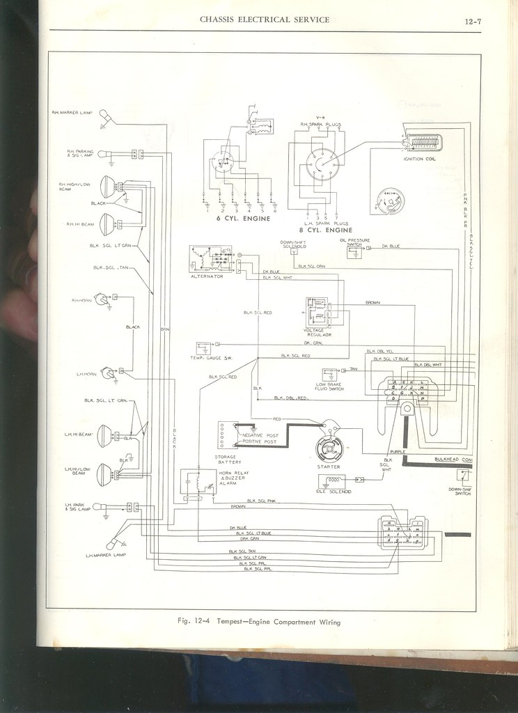
Diagrams of ignition wiring illustrate the wires used to power the vehicle’s electrical supply. There are usually four colors-coded terminus of each part. For accessories, red is for starter solenoid, blue for battery and blue for accessory. The “IGN” terminal is used to start the car and operate the wipers and other operating functions. This diagram demonstrates how to connect ACC and ST terminals with the rest of the components.
The battery is attached to the terminal named BAT. The electrical system can’t start without the battery. In addition, the switch will not start. If you don’t know the location of your car’s battery situated, you can examine the wiring diagram of your car to determine the best way to find it. The accessory terminals of your car are connected with the battery and ignition button. The BAT terminal connects to the battery.
Some ignition switches include an additional position in which users can modify their outputs as well as control them without needing to use the ignition. Sometimes, customers want to utilize the auxiliary output separate from the ignition. Use the additional output by connecting the connector to the ACC terminal on the switch that has the same color. This is a useful feature, but there is an important difference. Some ignition switches are configured to be in an ACC position once the car is in the ACC position. They will also be in START mode once the vehicle is entered the IGN position.
Gallery of 1969 Gto Ignition Switch Wiring Diagram
Gallery of 1969 Gto Ignition Switch Wiring Diagram


