Mercury Ignition Switch Wiring Diagram – Let’s start by looking at the different types of terminals on the ignition switch. These are terminals for the Ignition, Coil, or Accessory. Once we have identified what these terminals do, we will determine the various components in the ignition wiring. We’ll also discuss the functions of both the Ignition Switch and Coil. We will then discuss the function of the Ignition switch and Coil.
Terminals for ignition switches
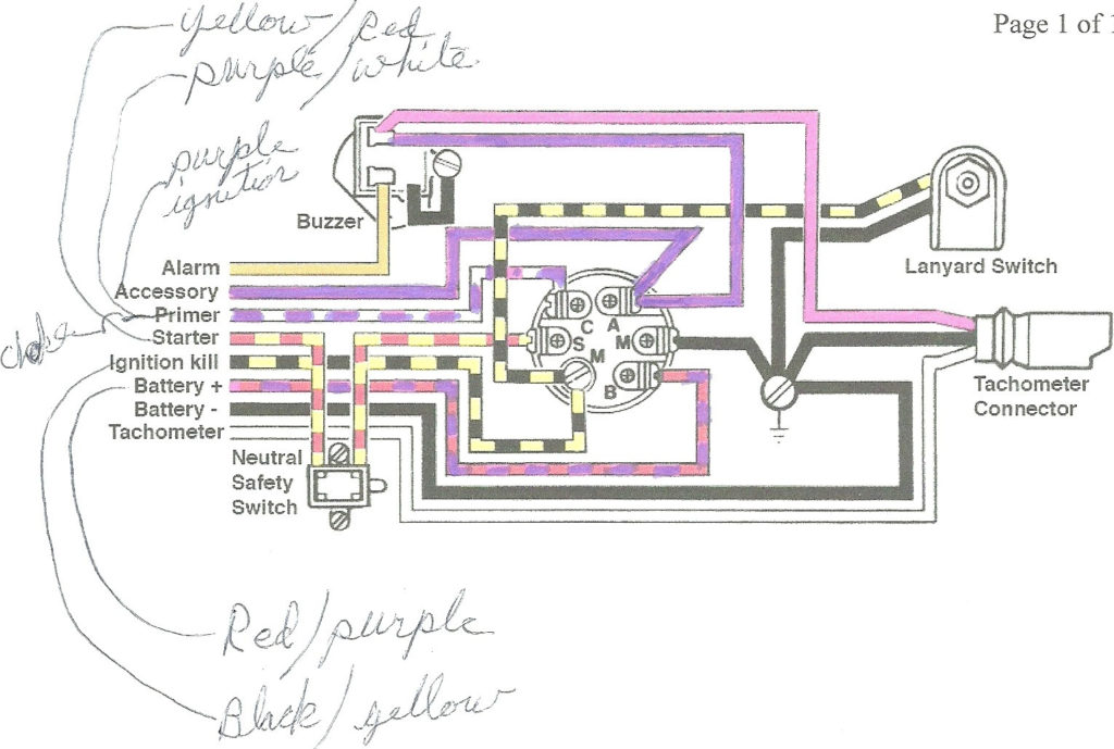
An ignition switch is comprised of three switches. They feed the voltage of the battery to different places. The first is used to turn on the choke through pushing it. Then, the third switch is used to control the ON/OFF position. Different manufacturers utilize their own color-coding method for the various conductors, that is described in a separate article. OMC employs this system. The connector allows for the attachment of a speedometer the ignition switch.
While many ignition switch terminals might not be authentic, the numbering of each one might not match the diagram. Before plugging into the ignition switch, be sure to test the continuity. This can be done with a cheap multimeter. After you’re satisfied with the quality of the connection then you can connect the new connector. The wiring loom for the ignition switch supplied by the manufacturer will differ from the one that you have in your car.
Before connecting the ACC outputs to your car’s auxiliary outputs It is essential to understand the basics of these connections. The ACC terminals and IGN terminals function as the standard connections for the ignition switch. The START and IGN connections are the most important connections for radio and stereo. The ignition switch is the one that turns the car’s engine to and off. Older cars are identified by the initials “ACC”, “ST”, (for individual magneto cables) on their ignition switch’s terminals.
Terminals for coil
The first step to determine the kind of ignition coil is to comprehend the terms that is used. The fundamental diagram of ignition wiring depicts various connections and terminals. There are two primary and secondary connections. Each coil has a specific operating voltage. To determine what kind of coil you have, the first step is to check the voltage at S1, which is the primary terminal. S1 should be checked for resistance to determine if the coil belongs to Type A, B, and/or C.
The negative of the chassis must be connected to the side of low-tension. It is also the ground on the diagram of ignition wiring. The high-tension component supplies the spark plugs with positive. To prevent noise the body of the coil must be connected to the chassis. But, it’s not required to connect electrically. The wiring diagram for the ignition will explain how to connect the two terminals of the positive or negative coils. It is possible to find an issue with the ignition coil that can be easily diagnosed by scanning it at an auto parts retailer.
The black-and-white-striped wire from the harness goes to the negative terminal. The other white wire has a black color and connects to the negative terminal. The black wire connects to the contact breaker. If you’re unsure of the connections of the two, try using a paper clip to remove them from the plug housing. Check that the terminals aren’t bent.
Accessory terminals
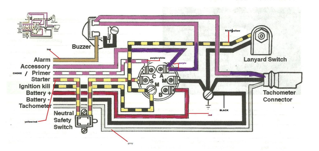
Diagrams of ignition wiring depict the wiring used in the vehicle’s power supply. Each component has four distinct colored connections. Red is used for accessories while yellow is the battery, while green is the starter solenoid. The “IGN” terminal can be used to start the car , and also to operate the wipers, as well as other operating functions. The diagram shows the connection between the ACCand ST terminals.
The terminal BAT is the connector for the battery. The electrical system can’t start without the battery. In addition, the switch will not start. A wiring diagram can inform you the location of the battery in your car. The accessory terminals in your car are connected to the battery and the ignition switch. The BAT terminal is connected to the battery.
Certain ignition switches have an additional position in which users can modify their outputs and manage them without needing to use the ignition. Users may wish to utilize the auxiliary output separately from the ignition. Use the auxiliary output by connecting the connector to the ACC terminal on your switch with the same colors. This option is useful however, it does have one key differentiator. The majority of ignition switches are set to operate in the ACC position when the car is in the ACC position, but they’re set to the START position when the vehicle is in the IGN position.
Gallery of Mercury Ignition Switch Wiring Diagram
Gallery of Mercury Ignition Switch Wiring Diagram


