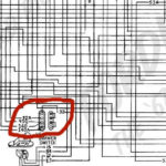
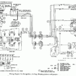
1971 Ford F100 Ignition Wiring Diagram – Let’s first take a look at the different types of terminals that are used in the ignition switch. These are the terminals used for Coil, Ignition Switch, and Accessory. After we’ve identified which terminals are used, we can begin to determine the various components of the 1971 Ford F100 Ignition Wiring Diagram. In addition, we will discuss the different functions of the Ignition Switch and Coil. After that, we’ll turn our attention to the Accessory terminals.
Terminals of ignition switch
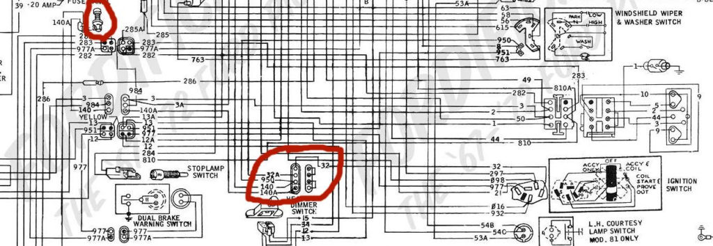
An ignition switch is composed of three switches. These are the ones that supply the battery’s power to various places. The first switch provides power to the choke while the second toggles the ON/OFF status of the ignition switch. Different manufacturers use various color codes for the various conductors. This is discussed in another article. OMC utilizes this method. This connector allows the connection of a speedometer to the ignition switch.
While most ignition switch terminals may not be original, the numbering for each one may not be in line with the diagram. To ensure that the wires are correctly connected to the switch it is recommended to check their continuity. This can be done using an inexpensive multimeter. Once you’re satisfied about the continuity of your wires, you’ll be able to connect the new connector. If your car has an ignition switch that is installed the wiring diagram will differ.
In order to connect the ACC outputs to the auxiliary outputs of your vehicle, you have to first understand how these two connections work. The ACC/IGN connections function as the default connections on the ignition switch. The START/IGN terminals are connected to the stereo or radio. The ignition switch is responsible for turning the engine of your car to and off. Older cars are equipped with ignition switch terminals labeled “ACC” or “ST” (for individual magnetowires).
Terminals for coil
Understanding the terminology is the first step to knowing what type of ignition coil you own. You’ll see a number of connections and terminals in an ignition wiring schematic, including two primary, and two secondary. The voltage that operates on each coil differs. This is why it is crucial to test the voltage at S1 (primary terminal). It is also recommended to examine S1 for resistance to identify if it’s a Type A B, C, or coil.
The coil’s low-tension component must be connected with the chassis’ positive. This is what you find in the wiring diagram. The high-tension side supplies the positive power direct to the spark plugs. The metal body of the coil needs to be connected to the chassis for suppression purposes however it isn’t electrically necessary. The wiring diagram for the ignition will demonstrate how to connect the two terminals of the negative or positive coils. In some cases it is recommended to conduct a scan at the local auto parts store will help identify the malfunctioning ignition coils.
The black-and-white-striped wire from the harness goes to the negative terminal. The terminal that is negative is served by the trace in black that’s attached to the white wire. The black wire connects to the contactbreaker. To verify the wires’ connections, use a paperclip to remove them from the housing. Make sure that the terminals aren’t bent.
Accessory terminals
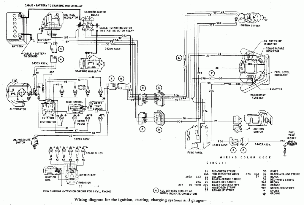
Diagrams of ignition wiring show the wires that are used in the power supply of the vehicle. There are usually four color-coded terminus for each component. Red is used to indicate accessories, yellow to the battery, and green is the starter solenoid. The “IGN” terminal is used to start the car, operating the wipers, and for other functions. The diagram demonstrates how to connect the ACC and ST terminals to the rest of the components.
The terminal BAT is the connection to the battery. The electrical system won’t start without the battery. A dead battery could cause the switch to not come on. To locate your car’s battery look over your wiring diagram. The accessory terminals in your vehicle are connected to the battery and the ignition switch. The BAT terminal is connected to the battery.
Some ignition switches include an accessory position where users can modify their outputs and control them without having to turn on the ignition. Sometimes, customers would like the auxiliary output to be operated independently of the ignition. To allow the auxiliary output to be used, connect the connector in the same shade as the ignition. Then , connect it to the ACC end of the switch. This feature of convenience is fantastic however, there’s one differentiator. Most ignition switches will be in an ACC position when the vehicle is in ACC however they will be in the START position if the car is in IGN.
Gallery of 1971 Ford F100 Ignition Wiring Diagram
Gallery of 1971 Ford F100 Ignition Wiring Diagram


