7 Prong Ignition Switch Wiring Diagram – The first step is to look at the different terminals on the ignition switch. These terminals are used for the Ignition button, Coil and Accessory. Once we have established the purpose of these terminals are used for, we will proceed to determine the various parts of the 7 Prong Ignition Switch Wiring Diagram. We’ll also go over the functions for the Ignition switch as well as the Coil. Next, we’ll discuss the functions of the Ignition switch and Coil.
Terminals for ignition switch
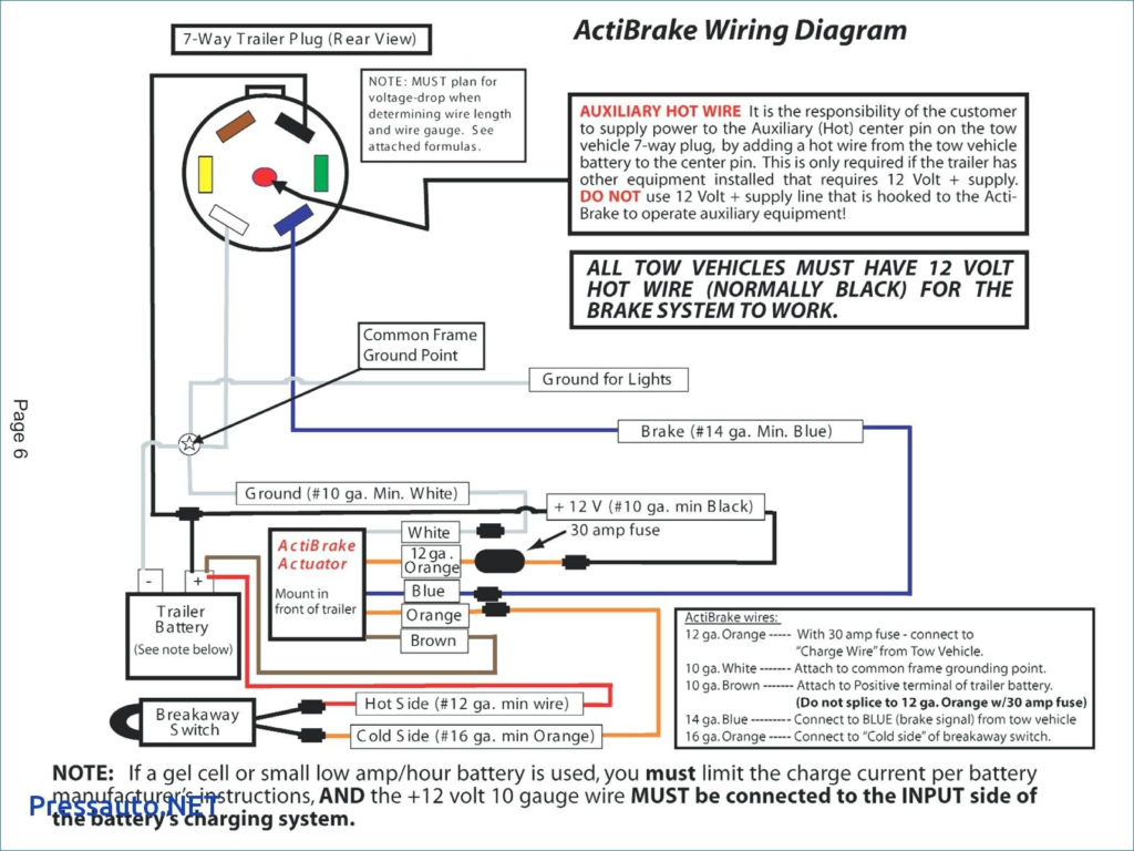
An ignition switch contains three different switches that direct the battery’s current to various locations. The first switch supplies power to the choke when it is pushed. The third is the switch that controls the ignition’s ON/OFF positions. Different manufacturers use different colors-coding systems to match the conductors. OMC utilizes this method. The ignition switch comes with an option to connect an tachometer.
While many ignition switch terminals don’t appear in their original configuration however, the numbers may not match that of the diagram. It is important to first verify the integrity of the wires to see if they are plugged into the ignition switch in the correct way. This can be checked using a simple multimeter. After you’re satisfied with the connection then you can connect the new connector. The wiring loom in an ignition system switch that is supplied by the manufacturer is distinct.
Before connecting the ACC outputs to your car’s auxiliary outputs, it is important to be familiar with the fundamentals of these connections. The ACC terminals and IGN terminals function as the primary connections to your ignition switch. The START and IGN connections are the most important connections for stereo and radio. The ignition switch is the one that turns the engine of your car on and off. The terminals of older cars’ ignition switches are labeled by “ACC” as well as ST (for the individual magneto wires).
Terminals for coil
Understanding the terminology is the initial step in knowing what type of ignition coil you have. In a basic ignition wiring diagram you’ll see a number of different terminals and connections, including two primary and two secondary. The coils come with a distinct operating voltage, and the first step in determining which type you’re using is to test the voltage on S1, the primary terminal. S1 should be examined for resistance to identify if the coil is type A, B or C.
The chassis’ negative must be connected to the coil’s low-tension side. This is what you see on the wiring diagram. The high-tension supply provides the spark plugs with positive electricity directly. The aluminum body of the coil needs to be connected to the chassis to prevent it from being smothered however it’s not electrically required. The wiring diagram of the ignition will demonstrate how to connect the terminals of either the negative or positive coils. In certain instances it is recommended to conduct a scan at your local auto parts store will help identify the malfunctioning ignition coils.
The black-and-white-striped wire from the harness goes to the negative terminal. The white wire is the other one. It has a black trace on it, and it connects to the positive terminal. The black wire is connected to the contact breaker. To check the connections, use a paperclip or a pencil to pull them out from the plug housing. Be sure to verify that the connections have not been bent.
Accessory terminals
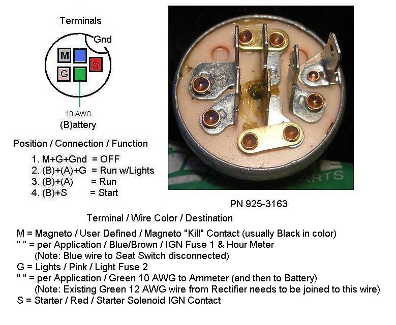
The wiring diagrams of the ignition illustrate the various wires that are used to power various components of the vehicle. There are typically four colors of terminals connected to each part. Red stands for accessories, yellow represents the battery and green is for the starter solenoid. The “IGN” terminal is used to turn on the car, turn on the wipers, as well as other functions. The below diagram shows how to connect both the ACC terminal as well as the ST terminals to the other components.
The battery is connected to the terminal called BAT. The electrical system can’t start without the battery. In addition, the switch will not begin to turn on. To locate your car’s battery, check your wiring diagram. The accessory terminals in your vehicle are connected to the battery and the ignition switch. The BAT terminal connects to the battery.
Some ignition switches come with an additional “accessory position” that lets users modify their outputs independent of the ignition. In some cases, users may want to utilize the auxiliary output separately from the ignition. In order to use the additional output, wire the connector in the same colors as the ignition connecting it to the ACC terminal on the switch. While this is an excellent feature, there’s something to be aware of. The majority of ignition switches have an ACC position when the vehicle is in ACC however they’ll be in the START position when the vehicle is in IGN.
Gallery of 7 Prong Ignition Switch Wiring Diagram
Gallery of 7 Prong Ignition Switch Wiring Diagram


