1972 Chevy C10 Ignition Wiring Diagram – The first step is to look at the different terminals that are used in the ignition switch. These are terminals for the Ignition, Coil, or Accessory. After we’ve identified the purpose of the terminals we will be able to identify the various parts of the ignition wiring. We’ll also discuss the functions of the Ignition switch, as well as the Coil. Then, we’ll talk about the functions of the Ignition switch and Coil.
Terminals for ignition switches
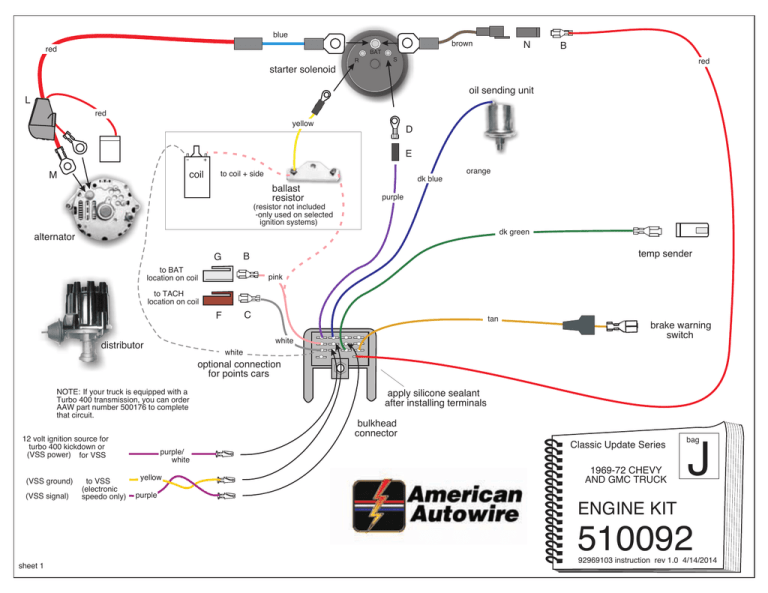
The ignition switch is comprised of three switches that supply the battery’s current to different locations. The first switch provides power to the choke, while the second switch controls the state of the switch. Each manufacturer has their own color-coding system, which we will discuss in another article. OMC uses this method. The ignition switch also includes a connector for adding the Tachometer.
Even though most ignition switch terminals don’t have an original number, they might have a different number. You should first check the continuity of the wires to ensure that they are connected to the ignition switch in the correct way. This can be done using a cheap multimeter. When you’re satisfied that the wires are in good continuity and you are able to connect the new connector. If your car has an original ignition switch supplied by the factory (or wiring loom) the wiring loom may differ from that in the car.
It is essential to know the way that ACC outputs and the auxiliary outputs work in order to connect them. The ACC and IGN connectors are the default connections for your ignition switch. Although the START, IGN, and ACC terminals are the primary connections for radios or stereo, the START/IGN connections are the most important ones. The ignition switch is responsible to turn the car’s engines on and off. Older vehicles are identified with the alphabets “ACC”, “ST”, (for individual magneto cables) at the ignition switch terminals.
Coil terminals
Understanding the terms is the initial step in determining which type of ignition coil you’ve got. A basic ignition wiring layout will provide you with a range of connections and terminals. The coils come with a distinct operating voltage. The first step in determining which type you’re using is to test the voltage at S1, the primary terminal. S1 should also undergo resistance tests to determine if it are a Type A or B coil.
The coil’s low-tension end is to be connected to the chassis’ positive. This is also the ground for an ignition wiring diagram. The high-tension side supplies positive direct to the spark plugs. To prevent noise, the coil’s metal body must be connected to the chassis. However, it is not necessary to connect the coil electrically. It is also possible to see the connections between the positive and negative coil’s terminals on the diagram of the ignition wiring. In certain instances, you’ll find that an ignition coil that is malfunctioning can be diagnosed with a scan in an auto parts store.
The black-and-white-striped wire from the harness goes to the negative terminal. The negative terminal is served by the black trace joined to the white wire. The black wire connects to the contact breaker. To check the wires’ connections, use a paperclip to lift them off the housing. Make sure that the connectors aren’t bent.
Accessory terminals
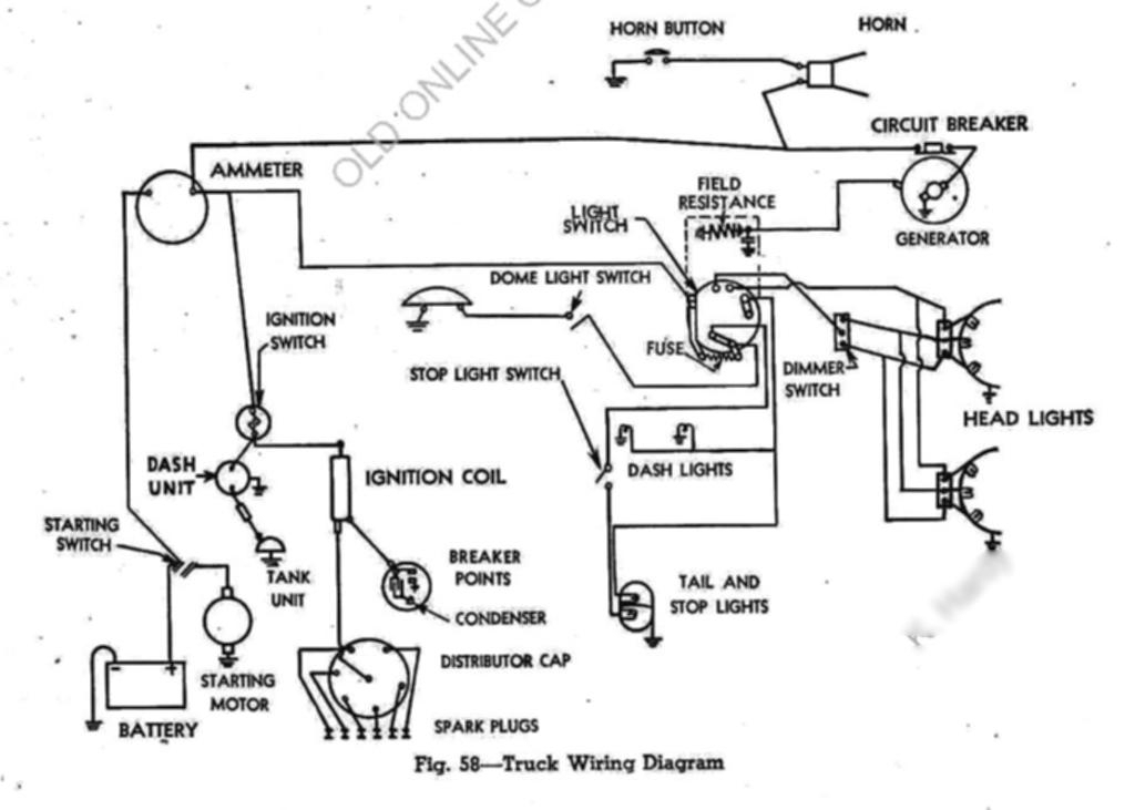
The ignition wiring diagrams illustrate the different wires that are used to power the car’s various parts. Typically there are four colors-coded terminals that are used for each component. For accessories, red stands for starter solenoid, yellow for battery, and blue is for accessories. The “IGN” terminal can be used to turn on the car, operate the wipers and other functions. The diagram illustrates how you can connect ACC or ST terminals and the rest.
The terminal BAT is the connection for the battery. The electrical system will not start without the battery. The switch will not turn off if the battery isn’t present. It is possible to look up your wiring diagram to figure out the location of your car’s batteries. placed. The ignition switch is connected to the car’s battery. The BAT terminal is connected to the battery.
Certain ignition switches have an accessory position where users can modify their outputs and control them without needing to use the ignition. Some customers prefer to make use of an additional output independent of the ignition. To use the auxiliary output, wire the connector using the same colors as ignition, connecting it to the ACC terminal on the switch. This is an excellent feature, but there is one important distinction. Most ignition switches are designed to have an ACC status when the car is in either the ACC or START positions.
Gallery of 1972 Chevy C10 Ignition Wiring Diagram
Gallery of 1972 Chevy C10 Ignition Wiring Diagram


