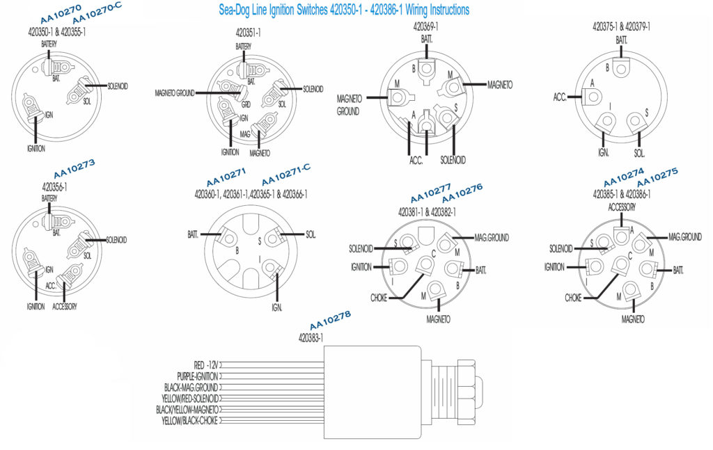
7 Terminal Ignition Switch Wiring Diagram – We’ll begin by looking at the various types terminals found in an ignition switch. These include the terminals that are for the Ignition switch, Coil, and Accessory. Once we’ve established the purpose of the terminals we can identify the various parts of the ignition wiring. In addition, we will discuss the roles of both the Ignition Switch and Coil. Then, we’ll talk about the functions of the Ignition switch as well as Coil.
Terminals of ignition switch
Three switches are located on the ignition switch. Each of these switches is able to feed the battery’s voltage to several different places. The first switch powers the choke. The third switch regulates the ON/OFF function of the ignition switch. Every manufacturer has its individual color-coding system that we’ll discuss in a subsequent article. OMC employs this system. Connectors can be connected to the ignition switch in order to connect an electronic Tachometer.
Although the majority of ignition switch terminals may not be authentic, the numbering of each might not be consistent with the diagram. Before you plug in the ignition switch, make sure to check the continuity. This can be done using an inexpensive multimeter. Once you’re satisfied about the integrity of the wires, then you’ll be able install the new connector. If your vehicle has an original factory-supplied ignition switch (or an electrical loom), the wiring loom may differ from the one in your vehicle.
Understanding how the ACC outputs are connected to the other outputs inside your vehicle is crucial. The ACC terminals as well as the IGN terminals are the primary connections to the ignition switch. The START and IGN connections are the main connections for stereo and radio. The ignition switch switches the car’s engine on and OFF. The terminals on older cars ignition switches are identified by “ACC” as well as ST (for the individual magneto wires).
Coil terminals
The terms used to define the model and type of the ignition coil is the most important thing. The fundamental diagram of ignition wiring illustrates a variety of connections and terminals. There are two primary and secondary connections. The coils are equipped with a particular operating voltage. The first step in determining which type you’re using is to test the voltage of S1 the main terminal. S1 should also be checked for resistance to determine if it’s an A, Type B or A coil.
The coil’s low-tension component is to be connected to the chassis’ positive. This is also the ground on the wiring diagram for ignition. The high-tension side connects the spark plugs to a positive. The metal body of the coil needs to connect to the chassis to prevent it from being smothered however it isn’t electrically required. The wiring diagram of the ignition will demonstrate how to connect the terminals of either the negative or positive coils. You may find an ignition coil problem that is easily identified by looking it up at the auto parts shop.
The black-and-white-striped wire from the harness goes to the negative terminal. The terminal for the negative is served by the trace in black that’s joined to the white wire. The black wire goes to the contact breaker. You can examine the connections using a paperclip to remove the wires of the housing. It’s also crucial to make sure that the terminals don’t bend.
Accessory terminals
Diagrams of ignition wiring depict the wiring used in the vehicle’s power supply. There are typically four colors of terminals connected to each part. Red is used for accessories and yellow is for the battery, while green is the starter solenoid. The “IGN” terminal is used to start the car, operate the wipers, as well as other features. This diagram shows how to connect ACC and ST terminals with the rest of components.
The battery is attached to the terminal named BAT. The electrical system can’t begin without the battery. Additionally, the switch won’t start. You can refer to your wiring diagram if not sure where the batteries of your car are. The accessory terminals in your car connect to the ignition switch, as well as the battery. The BAT terminal is connected to the battery.
Certain ignition switches have an additional position in which users can adjust their outputs as well as control them without having to turn on the ignition. Sometimes, customers may wish to utilize the auxiliary input independently of the ignition. You can utilize the additional input by connecting it to the ACC terminal. While this is a convenient option, there’s an important difference. Most ignition switches are configured to have an ACC position when the car is in the ACC position, whereas they’re in the START position when the vehicle is in the IGN position.
Gallery of 7 Terminal Ignition Switch Wiring Diagram
Gallery of 7 Terminal Ignition Switch Wiring Diagram


