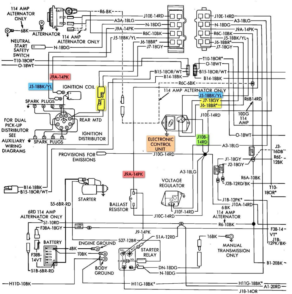
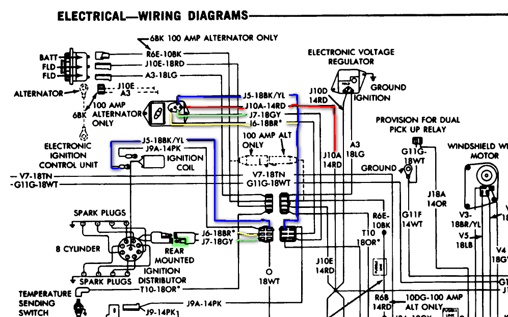
1975 Dodge Truck Ignition Wiring Diagram – We will first look at the various types and purposes of the terminals on the ignition switches. The terminals are the Ignition switch and Coil as well as the Accessory. After we’ve identified the purpose of the terminals it is possible to recognize the various parts of the ignition wiring. We’ll also discuss the functions as well as the Coil. After that, we will concentrate on the accessories terminals.
Ignition switch terminals
Three switches can be found on the ignition switch. Each of these switches is able to feed the battery’s voltage to several different destinations. The first one is used to turn on the choke by pushing it, and the third switch is used to control the ON/OFF setting. Different manufacturers use different color-coding methods to identify different conductors. We’ll discuss this in another article. OMC utilizes this system. A connector is also included inside the ignition switch for attaching a to a tachometer.
While most ignition switch terminals can be duplicated, the numbers may not be in line with the diagram. The first step is to check the continuity of all wires to ensure that they are properly plugged into the ignition switches. This can be checked with a multimeter that is inexpensive. When you’re happy with the continuity, you can place the new connector. The wiring loom for the ignition switch supplied by the factory will be different from the one in your car.
Before you can connect the ACC outputs to your car’s auxiliary outputs, it is important to understand the basics of these connections. The ACC and IGN connectors are the default connections for the ignition switch. The START, IGN, and ACC terminals are the primary connections for radios or stereo, the START/IGN terminals are the main ones. The ignition switch is the one that controls the engine of your car. On older cars the ignition switch’s terminals are identified with the alphabets “ACC” as well as “ST” (for the individual magnet wires).
Terminals for coil
The first step in determining the kind of ignition coil is to comprehend the terminology used. The basic ignition wiring diagram shows a number different connections and terminals. There are two primary and one secondary. Each coil comes with its own operating voltage. To determine which type of coil you have the first step is to check the voltage at S1, the primary terminal. S1 should also undergo resistance testing to determine whether it’s an A or B coil.
The lower-tension side of the coil must be connected to the chassis’ negative. This is also the ground on the ignition wiring diagram. The high-tension supply provides positively directly to spark plugs. For suppression purposes, the coil’s metal body must be connected to chassis. It is not required to connect electrically. The wiring diagram for ignition will also outline the connection of the positive coil terminals. Sometimes, an inspection at an auto parts shop can detect a defective ignition wire.
The black-and-white-striped wire from the harness goes to the negative terminal. The white wire is black-colored and connects to the terminal opposite. The black wire is connected to the contact breaker. To verify the connections between the two wires, employ a paperclip to remove them off the housing. It is also important to make sure the terminals do not bend.
Accessory terminals
The ignition wiring diagrams show the various wires utilized for powering the different components. There are typically four color-coded terminals to each component. The red color is used for accessories and yellow is for the battery, and green is for the solenoid for starters. The “IGN” terminal is used to start the car, controlling the wipers, and for other functions. The diagram shows the connection between the ACC- and ST terminals.
The terminal referred to as BAT is the place where the battery is. The battery is necessary to allow the electrical system to get started. A dead battery can cause the switch to not turn on. It is possible to view your wiring diagram to determine where the batteries of your car are placed. The accessory terminals on your car are connected to the battery and the ignition switch. The BAT connector is connected to your battery.
Some ignition switches feature an “accessory” setting that permits users to control their outputs without needing to turn on the ignition. Sometimes, customers may wish to utilize the auxiliary output separately from the ignition. You can use the secondary output by connecting the connector to an ACC terminal on your switch with the same colors. This is a useful feature, however there’s an important distinction. Many ignition switches can be configured to be in an ACC position when the vehicle has been moved into the ACC position. They’ll also be in the START position once the vehicle is entered the IGN position.
Gallery of 1975 Dodge Truck Ignition Wiring Diagram
Gallery of 1975 Dodge Truck Ignition Wiring Diagram


