Mazda 323 Ignition Wiring Diagram – We’ll begin by looking at different types of terminals on the ignition switch. These terminals include the Ignition switch as well as the Coil as well as the Accessory. After we’ve identified the purpose of these terminals and what they do, we can then determine the various components in the ignition wiring. In addition, we will discuss the functions of the Ignition switch, and Coil. Then, we’ll focus on the accessory terminals.
The terminals are for ignition switches.
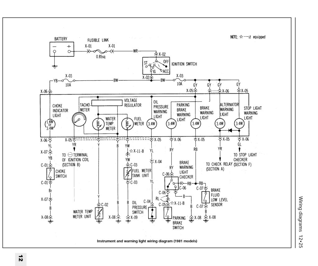
An ignition switch has three switches. They feed the battery’s voltage to different locations. The choke is powered by the first switch. The third switch regulates the ON/OFF switch of the ignition switch. Different manufacturers have different color-coding systems for different conductors. This will be covered in a separate article. OMC follows this procedure. The ignition switch is also equipped with an adapter for the addition of an tachometer.
While the majority of the ignition switch terminals aren’t original, the numbering for each may not match the diagram. Verify the electrical continuity first to ensure that they’re properly connected to the ignition switch. This can be done with a simple multimeter. Once you’ve verified the continuity of the wires you can then connect the connector. If your car has an installed ignition switch the wiring diagram will differ.
It is important to know the differences between ACC and the auxiliary outputs. The ACC, IGN and START terminals are the primary connections to the ignition switch. They are also the main connections to the radio and stereo. The ignition switch is responsible to turn the engine of your car on and off. Older cars are identified with the alphabets “ACC”, “ST”, (for individual magneto cables) on their ignition switch terminals.
Coil terminals
The first step in determining the type of ignition coil is to comprehend the terms used. A basic ignition wiring diagram will display a range of terminals and connections which include two primary terminals and two secondaries. The operating voltage of every coil is different. It is essential to first check the voltage at the S1 (primary terminal). You should also examine S1 for resistance in order to identify if it’s an A B, C, or coil.
The negative of the chassis must be connected to the side of low-tension. This is the ground in the wiring diagram for ignition. The high-tension side delivers the positive power direct to the spark plugs. The coil’s metal body needs to be connected to the chassis to suppress the effect, but it is not electrically essential. The wiring diagram for the ignition will show you how to connect the terminals of either the positive and negative coils. In some cases it is possible to find a malfunctioned ignition coil is identified by scanning at an auto parts store.
The black-and-white-striped wire from the harness goes to the negative terminal. The positive terminal is connected to the white wire with an trace of black. The black wire connects to the contactbreaker. To verify the connections between the two wires, employ a paperclip to remove them out of the housing. Make sure you verify that the connections have not been bent.
Accessory terminals
Diagrams of ignition wiring illustrate the wiring used to power the vehicle’s electrical supply. There are usually four different colors of terminals connected to each part. The red color is used for accessories and yellow is for the battery, while green is for the solenoid for starters. The “IGN” terminal can be utilized to turn on the car, operate the wipers, as well as other functions. The diagram shows how you can connect the ACC and ST terminals to the rest of the components.
The terminal BAT is the connector for the battery. The electrical system won’t start without the battery. In addition the switch isn’t turned on. If you’re not sure of the exact location where the battery in your car is situated, you can look at your wiring diagram to see the best way to find it. The accessory terminals of your car are connected to the ignition switch, as well as the battery. The BAT terminal connects to the battery.
Some ignition switches come with the option of an “accessory position” which allows users to alter their outputs without the ignition. Sometimes, customers want to utilize an auxiliary output that is separate from the ignition. The auxiliary output is utilized to connect the connector in the same colors as your ignition, and then connecting it to the ACC terminal of the switch. This convenience feature is great, but there is one distinction. Most ignition switches will be in an ACC position when the vehicle is in ACC however, they’ll be at the START position when the car is in IGN.
Gallery of Mazda 323 Ignition Wiring Diagram
Gallery of Mazda 323 Ignition Wiring Diagram


