1976 Mercury Outboard 500 50 Hp Ignition Switch Wiring Diagram – We will first look at the various types and functions of the terminals that are found in the ignition switches. These are terminals that are used for Coil, Ignition Switch, and Accessory. After we’ve established what these kinds of terminals are We will then discover the various components of the 1976 Mercury Outboard 500 50 Hp Ignition Switch Wiring Diagram. We will also discuss the roles of the Ignition switch, as well as the Coil. Following that, we will discuss the Accessory Terminals.
Terminals for ignition switches
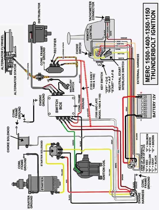
Three switches are located on an ignition switch. Each of these switches transmits the battery’s current to a variety of places. The first one supplies power to the choke whenever it is pushed. The second is the ignition switch’s ON/OFF position. Different manufacturers use different colors for different conductors. This is explained in a separate article. OMC follows this system. The connector allows for the connection of a speedometer to the ignition switch.
While most ignition switch terminals aren’t original, the numbering for each one may not be in line with the diagram. Check the electrical continuity first to ensure they’re connected correctly to the ignition switch. This can be checked with a multimeter that is inexpensive. When you are satisfied with the continuity of the wires, connect the new connector. If your vehicle has an ignition switch that is installed the wiring diagram will differ.
Before connecting the ACC outputs to the auxiliary outputs of your car, it is important to know the fundamentals of these connections. The ACC/IGN terminals function as the default connections for the ignition switch. The START/IGN terminals connect to the radio or stereo. The ignition switch is responsible for turning the car’s engine on and off. The terminals of older vehicles ignition switches are identified with “ACC” and ST (for individual magneto wires).
Terminals for coil
Understanding the terminology is the initial step towards finding out what kind of ignition coil you own. The diagram of the basic ignition wiring shows a number different connections and terminals. There are two primary and secondary connections. Each coil comes with its own operating voltage. To determine what kind of coil you own, the first step is to determine the voltage at S1, which is the primary terminal. S1 should also be tested for resistance in order to identify whether it’s a Type B, B, or A coil.
The low-tension coil side must be connected at the chassis’s plus. This is the wiring diagram you will see on the wiring diagram. The high tension side provides positive directly the spark plugs. To prevent noise the body of the coil is required to be connected to the chassis. But, it’s not necessary to electrically connect. The wiring diagram will depict the connection between positive and negative coil terminals. Sometimes, a check at an auto parts store could diagnose a malfunctioning ignition wire.
The black-and-white-striped wire from the harness goes to the negative terminal. The positive terminal receives the other white wire and the black trace. The black wire is connected to the contactbreaker. If you’re unsure of the connections of the twowires, use a paper clip to remove them from the housing of the plug. Be sure the terminals aren’t bent.
Accessory terminals
The ignition wiring diagrams illustrate the different wires that are used to power the car’s various components. Each component has four distinct connections that are color coded. Red stands for accessories, yellow for the battery, and green for the solenoid for starters. The “IGN” terminal can be used to start the car, turn on the wipers, as well as other features. The below diagram shows how to connect both the ACC terminal and ST terminals to other components.
The terminal BAT is the connection for the battery. The battery is necessary to allow the electrical system to get started. The switch will not turn off if the battery isn’t there. A wiring diagram can inform you where to find the battery of your car. The accessory terminals in your car are connected to the battery and ignition button. The BAT Terminal is connected to the battery.
Some ignition switches come with an accessory position. This lets users access their outputs from a different place without having to turn on the ignition. Sometimes, customers would like the auxiliary output to be used separately from the ignition. For the auxiliary output to be used, wire the connector with the same shade as the ignition. Connect it to the ACC end of the switch. This is a great convenience feature however, there’s one difference. A lot of ignition switches can be set to have an ACC position once the car is in the ACC position. They also will be in the START mode when the vehicle has entered the IGN position.
Gallery of 1976 Mercury Outboard 500 50 Hp Ignition Switch Wiring Diagram
Gallery of 1976 Mercury Outboard 500 50 Hp Ignition Switch Wiring Diagram


