4 Pin Ignition Switch Circuit Lucas Key Switch Wiring Diagram – We will first examine the various types of terminals found on the ignition switch. These terminals comprise the Ignition switch, the Coil along with the Accessory. Once we understand the function of each kind of terminal, we are able to identify the various components of the ignition wiring. In addition, we will discuss the function of the Ignition switch, as well as the Coil. Then we’ll proceed to the Accessory Terminals.
Terminals for the ignition switch
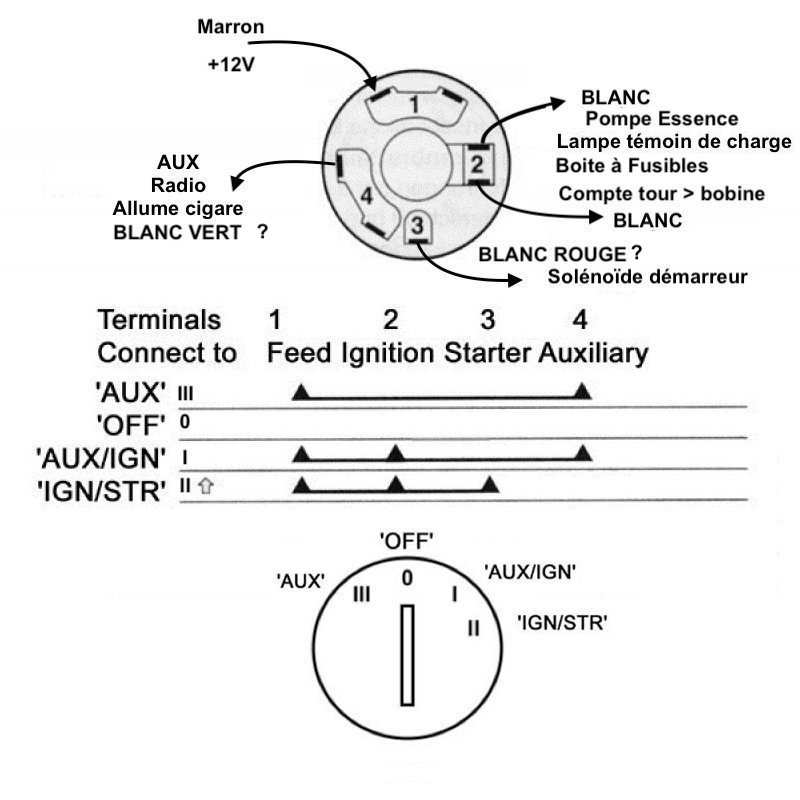
There are three switches on the ignition switch, and they transmit the battery’s current voltage to a variety of destinations. The ON/OFF setting of the ignition switch is controlled by the first switch, which delivers power to the choke whenever it’s pulled. Different manufacturers have different color-coding systems to identify different conductors. We will cover this in a different article. OMC follows this scheme. The ignition switch is also equipped with a connector for adding the Tachometer.
Although the majority of ignition switch terminals don’t have an original number, they may have a different number. It is important to first verify the integrity of the wires to ensure that they are plugged into the ignition switch in the correct way. You can check this using an inexpensive multimeter. After you’ve confirmed the continuity of the wires you can then connect the connector. If your vehicle is equipped with an ignition switch that is installed, the wiring diagram will differ.
In order to connect the ACC outputs to the auxiliary outputs of your vehicle, you have first know the way these two connections function. The ACC, IGN and START terminals are the default connection to the ignition switch. They also serve as the main connections to the radio and stereo. The ignition switch acts as the engine’s off/on button. Older vehicles have ignition switch’s terminals that are labeled “ACC” or “ST” (for individual magnetowires).
Terminals for coil
Understanding the terminology is the first step towards finding out what kind of ignition coil you have. The basic ignition wiring diagram shows a number different connections and terminals. There are two primary and secondary connections. Each coil has an operating voltage. The first step in determining which kind you’re using is to examine the voltage of S1 or the primary terminal. S1 must also go through resistance testing to determine if it are an A or B coil.
The coil’s low-tension component must be connected to the chassis positive. This is the ground of the ignition wiring. The high-tension part connects the spark plugs to a positive. For suppression purposes the body of the coil is required to be connected to the chassis. However, it is not necessary to electrically connect. There are also connections of the negative and positive coil’s terminals on an ignition wiring diagram. There could be an issue with your ignition coil that can be easily diagnosed by looking it up at the auto parts shop.
The black-and-white-striped wire from the harness goes to the negative terminal. The positive terminal is connected to the white wire and a trace of black. The black wire connects to the contactbreaker. To confirm the connection, make use of a paperclip or pencil to lift them out from the plug housing. You should also check to ensure that the terminals are not bent.
Accessory terminals
Diagrams of ignition wiring depict the wires that provide power to various components of the vehicle. There are typically four different color-coded terminus for each component. Red stands for accessories, yellow represents the battery, and green for the starter solenoid. The “IGN” terminal is used to start the vehicle and control the wipers as well as other operational functions. The diagram shows how to connect ACC or ST terminals, and other.
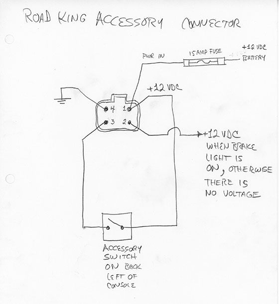
The terminal BAT holds the battery. The electrical system can’t be started without the battery. Additionally, the switch will not turn on without the battery. To locate your car’s battery examine the wiring diagram. The ignition switch and the battery are connected through the accessory terminals. The BAT connector connects to your battery.
Certain ignition switches have an independent “accessory” position, where users can manage their outputs without the ignition. Sometimes, customers want to use the auxiliary output separate from the ignition. It is possible to use the auxiliary input by connecting the connector to the ACC terminal. This convenience feature is great however there’s a differentiator. Many ignition switches have the ACC position when your car is in ACC mode and a START position when it is in IGN.
Gallery of 4 Pin Ignition Switch Circuit Lucas Key Switch Wiring Diagram
Gallery of 4 Pin Ignition Switch Circuit Lucas Key Switch Wiring Diagram


