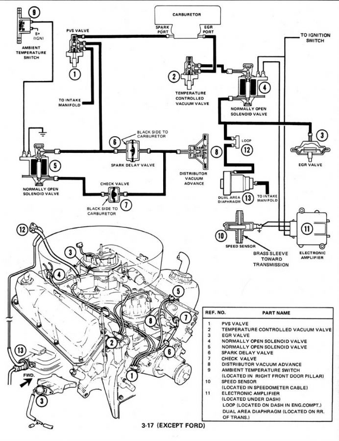
1977 Ford F250 Custom Ignition Wiring Diagram – The first step is to take a look at the different types of terminals that are used in the ignition switch. These are the terminals that connect the Ignition, Coil, or Accessory. After we’ve identified what these terminals are and what they do, we can then be able to identify the various parts of the ignition wiring. We’ll also discuss the roles of both the Ignition Switch and Coil. We’ll then turn our attention on the accessory terminals.
The terminals of the ignition switch
Three switches can be found on an ignition switch. Each of these switches transmits the battery’s current to a variety of destinations. The ON/OFF position of the ignition switch is controlled by the first switch, which delivers the choke with power when it’s pulled. Different manufacturers have different color codes for different conductors. This is described in a separate article. OMC uses the same method. The adapter is attached to the ignition switch to allow the addition of a tonometer.
Although most ignition switch terminals are duplicated, the number may not be in line with the diagram. Before you plug into the ignition switch, ensure that you check the continuity. A multimeter is a great tool to test the continuity. When you’re happy with the quality of the connection then you can connect the new connector. The wiring loom used in an ignition system switch that is supplied by the manufacturer is different.
Before connecting the ACC outputs to the auxiliary outputs of your car, it is important to understand the basics of these connections. The ACC/IGN terminals function as the default connections for the ignition switch. The START/IGN connections connect to the radio or stereo. The ignition switch’s function is to turn the car’s engines on and off. The terminals of older cars’ ignition switches are labeled by “ACC” and ST (for specific magneto wires).
Coil terminals
Understanding the terminology utilized is the initial step in determining what kind of ignition coil you need. You will see several connections and terminals on an ignition wiring schematic, including two primary, as well as two secondary. Each coil operates at a specific voltage. The first step to determine the kind you have is to check the voltage at S1 or the primary terminal. S1 should also be tested for resistance to determine if the coil is an A, Type B, or A coil.
The negative end of the chassis must be connected to the coil’s low-tension end. This is what is known as the ground for the wiring for ignition. The high tension side provides positive directly the spark plugs. To prevent noise, the coil’s metal body must be connected to chassis. But, it’s not necessary to connect the coil electrically. The wiring diagram of the ignition will demonstrate how to connect the terminals of the positive and negative coils. In some cases, a scan at your local auto parts store can help you identify defective ignition coils.
The black-and-white-striped wire from the harness goes to the negative terminal. The white wire is the other one. It has a black trace on it, and it goes to the positive terminal. The black wire connects to the contact breaker. To confirm the connections, you can use a paperclip or a pencil to lift them out of the housing for the plug. Make sure that the terminals don’t bend.
Accessory terminals
The ignition wiring diagrams show the various wires that are used to power various components. There are usually four colored terminus lines for each component. The red symbol represents accessories, yellow is for the battery and green is for the solenoid for starters. The “IGN” terminal is used to start the car, control the wipers and other features. The following diagram shows how to connect the ACC terminal and ST terminals to other components.
The battery is connected to the terminal called BAT. The battery is vital for the electrical system to start. Additionally, the switch doesn’t turn on. If you don’t know where your car’s battery is situated, examine the wiring diagram of your car to determine where it is. The accessory terminals in your car connect to the ignition switch as well as the battery. The BAT terminal is connected to the battery.
Some ignition switches come with an additional “accessory position” that allows users to modify their outputs independent of the ignition. In some cases, users may want to use the auxiliary input separately from the ignition. Use the additional output by connecting it to an ACC terminal on your switch with the same colors. This convenience feature is great, but there is one difference. The majority of ignition switches are set to operate in the ACC position when the car is in the ACC position, but they’re set to the START position when the vehicle is in the IGN position.
Gallery of 1977 Ford F250 Custom Ignition Wiring Diagram
Gallery of 1977 Ford F250 Custom Ignition Wiring Diagram


