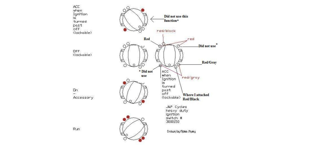
1982 Harley Ignition Switch Wiring Diagram – We’ll begin by looking at the various types of terminals on the ignition switch. These terminals serve for the Ignition button, Coil and Accessory. Once we’ve established the purpose of the terminals we can determine the various components of the ignition wiring. We will also cover the roles of both the Ignition Switch and Coil. Then, we’ll talk about the roles of the Ignition switch as well as Coil.
The terminals are for ignition switches.
An ignition switch contains three switches that supply the battery’s current to different destinations. The first switch is used to drive the choke through pushing it. Then, the second is for the ON/OFF setting. Different manufacturers use different color codes for various conductors. This is described in a different article. OMC follows the same system. Connectors can be attached to the ignition switch in order to add a digital tachometer.
Although some ignition switch terminals could not be original, the numbers of each may not match the diagram. Before plugging in the ignition switch, make sure to check the continuity. A multimeter that is inexpensive can assist you in this. After you’re sure that all wires are running in good harmony then you can connect the new connector. If your vehicle has an original ignition switch supplied by the factory (or an electrical loom), the wiring loom will differ from that in the car.
First, understand the differences between ACC and auxiliary outputs. The ACC/IGN terminals act as the default connections on the ignition switch. The START/IGN connections connect to the stereo or radio. The ignition switch controls the car’s engine. The terminals on older cars ignition switches are marked by “ACC” and ST (for the individual magneto wires).
Terminals for coil
The first step in determining the type of ignition coil is to understand the terms used. The fundamental diagram of ignition wiring illustrates a variety of connections and terminals. There are two primary and one secondary. You must determine the kind of coil you have by testing the voltage at the primary terminal S1. S1 should be checked for resistance to identify if the coil is Type A, B, or C.
The coil’s low-tension component is to be connected to the chassis positive. This is what you see on the wiring diagram. The high-tension supply supplies positive directly to spark plugs. To prevent noise the body of the coil must be connected to the chassis. But, it’s not required to connect electrically. The wiring diagram for ignition will also outline how to connect the positive coil terminals. In certain instances, a scan at your local auto parts store will help identify malfunctioning ignition coils.
The black-and-white-striped wire from the harness goes to the negative terminal. The other white wire has a black color and goes to the terminal opposite. The black wire connects to the contact breaker. If you’re not sure about the connection between the twowires, use the clip of a paperclip to remove them from the plug housing. Be sure the terminals aren’t bent.
Accessory terminals
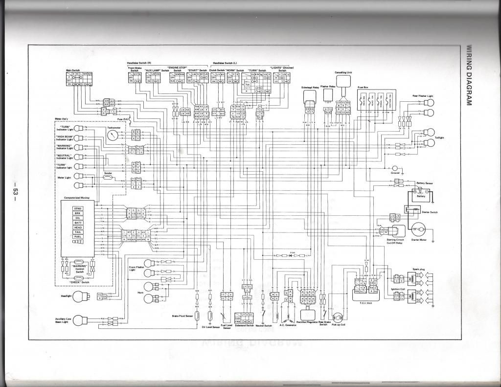
Ignition wiring diagrams depict the various wires utilized to power various components. There are generally four colors-coded terminus of each part. Red is used for accessories and yellow is for the battery, while green is the starter solenoid. The “IGN terminal is used to start the car, controlling the wipers and other functions. The diagram illustrates the connection of the ACCas well as ST terminals.
The terminal BAT connects the battery to the charger. The electrical system will not start if the battery isn’t connected. A dead battery could make the switch stop turning on. If you’re not sure of where your car’s battery is located, you can examine the wiring diagram of your car to determine where it is. The accessory terminals in your car are connected to the battery and the ignition switch. The BAT terminal is connected to the battery.
Certain ignition switches come with an “accessory” position that allows users to regulate their outputs without needing to turn on the ignition. Sometimes, a customer wants to use an auxiliary output that is separate from the ignition. For the auxiliary output to be used, connect the connector to the same shade as that of the ignition. Then , connect it to the ACC end of the switch. While this is an excellent feature, there’s one crucial distinction. Most ignition switches will have an ACC position if the car is in ACC, but they’ll be in the START position if the car is in IGN.
Gallery of 1982 Harley Ignition Switch Wiring Diagram
Gallery of 1982 Harley Ignition Switch Wiring Diagram


