1979 Ford F150 Ignition Switch Wiring Diagram – Let’s begin by looking at the different types terminals found on the ignition switch. These are terminals that are used for Coil, Ignition Switch, and Accessory. When we have a clear understanding of the purpose of each terminal, it is possible to determine the components of the ignition wiring. In addition, we will discuss the functions of both the Ignition Switch and the Coil. After that we will move on to the Accessory Terminals.
Terminals for ignition switch

Three switches can be found on an ignition switch. Each of these three switches transmits the battery’s current to a variety of locations. The first one supplies the choke with power when pushed, and the second is the ignition switch’s ON/OFF position. Different manufacturers have distinct colour-coding systems that correspond to the conductors. OMC uses this system. A connector is also included in the ignition switch for attaching an to a tachometer.
Even though the majority of ignition switch terminals don’t come in original form The numbering might not be in line with the diagram. The first step is to check the continuity of each wire to make sure they’re properly connected to the ignition switches. A multimeter that is inexpensive can assist you in this. When you’re satisfied with the continuity of the wires, then you’ll be able to connect the new connector. If your car has an original ignition switch supplied by the factory (or an electrical loom) The wiring loom might differ from the one in the car.
Knowing how the ACC outputs connect to the other outputs inside your car is essential. The ACC terminals as well as the IGN terminals are the standard connections for your ignition switch. The START and IGN connections are the main connections for radio and stereo. The ignition switch acts as the engine’s switch to turn off or on. Older cars are identified by the initials “ACC”, “ST”, (for individual magneto cables) at their ignition switch terminals.
Terminals for Coil
To identify the kind of ignition coil, the initial step is to understand the definition of. There are a variety of connections and terminals in an ignition wiring schematic that include two primary and two secondary. The voltage that operates on every coil is different. This is why it is important to first test the voltage at S1 (primary terminal). S1 should also undergo resistance tests to determine if it are an A or B coil.
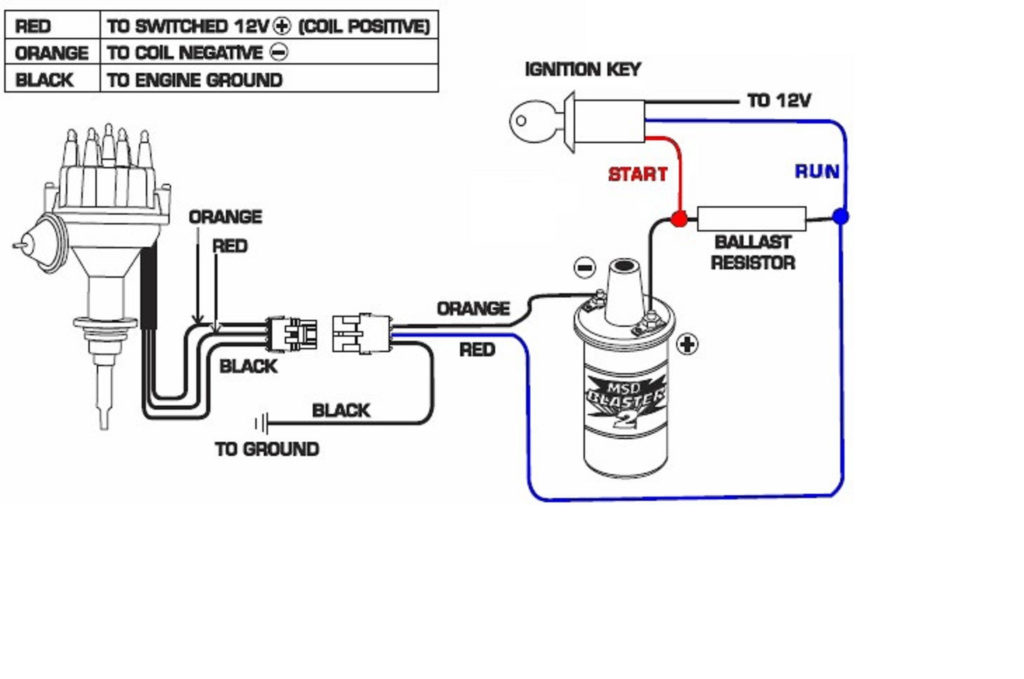
The low-tension side of the coil must be connected to the chassis’ negative. This is what’s called the ground on the wiring diagram for ignition. The high-tension side supplies the positive power directly to the spark plugs. For suppression purposes the coil’s body metal must be connected to the chassis. It is not required for electrical use. The diagram of the ignition wiring will also show you the connection of the positive and negative coil terminals. It is possible to find an ignition coil problem which can be identified by looking it up at an auto parts store.
The black-and-white-striped wire from the harness goes to the negative terminal. The positive terminal receives the white wire, which has an black trace. The black wire is connected to the contact breaker. You can take the black wire from the housing of the plug by using a paperclip in case you are uncertain about the connection. Also, make sure that the connections aren’t bent.
Accessory terminals
The ignition wiring diagrams show the different wires used to power various components. There are usually four colored terminals that correspond to the respective component. Red refers to accessories, yellow is the battery, and green the starter solenoid. The “IGN” terminal is used to turn on the vehicle and control the wipers as well as other operational functions. The diagram shows the connection to the ACCand ST terminals.
The terminal BAT holds the battery. The electrical system can’t be started without the battery. A dead battery could make the switch stop turning on. It is possible to view the wiring diagram of your car to see where your car’s batteries are located. The accessory terminals in your car are connected to the battery and ignition button. The BAT Terminal is connected to the Battery.
Some ignition switches have an “accessory” setting that allows users to control their outputs , without having to use the ignition. Some customers might want to utilize the auxiliary input separately from the ignition. You can use the secondary input by connecting the connector to the ACC terminal. Although this is a fantastic option, there’s a thing you should know. Most ignition switches come with an ACC position when the car is in ACC mode, and a START position when you are in IGN.
Gallery of 1979 Ford F150 Ignition Switch Wiring Diagram
Gallery of 1979 Ford F150 Ignition Switch Wiring Diagram


