1980 Jeep Cj7 Ignition Wiring Diagram – First, we will look at the different types of terminals in the ignition switch. These include the terminals for the Ignition switch, Coil, and Accessory. When we have a clear understanding of the purpose of each kind of terminal, we are able to identify the parts of the ignition wiring. We’ll also go over the functions for the Ignition switch, as well as the Coil. The next step is to focus on the accessory terminals.
Terminals for ignition switches
An ignition switch contains three different switches that direct the battery’s power to various destinations. The ON/OFF position of the ignition switch is controlled by the first switch, which provides power to the choke when it’s pushed. Different manufacturers use different color-coding methods for different conductors. This will be covered in another article. OMC follows this system. An adapter is included on the ignition switch that allows the installation of a Tachometer.
While most ignition switch terminals aren’t authentic, the numbering of each one may not be in line with the diagram. It is important to first verify the electrical continuity to see if they are plugged into the ignition switch correctly. A multimeter is an excellent instrument to verify the continuity. After you’re satisfied with the continuity of the wires, it is time to connect the new connector. The wiring loom of an ignition switch that is factory-supplied will be different than the one you have in your car.
For connecting the ACC outputs to the auxiliary outputs of your vehicle, you have to understand the way these two connections function. The ACC/IGN connections function as the default connection on the ignition switch. The START/IGN terminals are connected to the radio or stereo. The ignition switch’s function is to turn the engine of your car on and off. The terminals of the ignition switch on older cars are labeled with the alphabets “ACC” and “ST” (for individual magneto wires).
Terminals for coil
Understanding the terminology is the initial step to finding out what kind of ignition coil you have. A basic ignition wiring layout will show you a number of connections and terminals. The coils come with a distinct operating voltage. The initial step in determining which type you’ve got is to check the voltage at S1, the primary terminal. S1 must also be subjected to resistance tests to determine if it is an A or B coil.
The low-tension end of the coil should be connected to the chassis the negative. This is what you find in the diagram of wiring. The high-tension supply supplies positively directly to spark plugs. For suppression purposes, the coil’s metal body is required to be connected to the chassis. But, it’s not required to connect electrically. The wiring diagram will depict the connection between positive and negative coils. In some cases, you’ll find that an ignition coil that is malfunctioning is easily identified with a scan at an auto parts shop.
The black-and-white-striped wire from the harness goes to the negative terminal. The terminal that is negative is served by the black trace connected to the white wire. The black wire is connected to the contact breaker. To test the connections between the two wires, use a paperclip to lift them off the housing. It is also important to ensure that the terminals aren’t bent.
Accessory terminals
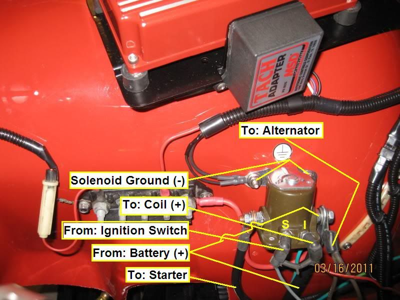
Ignition wiring diagrams depict the various wires utilized for powering the various components. There are generally four color-coded terminals to each component. The red color is used for accessories, yellow is for the battery, while green is the solenoid for starters. The “IGN” terminal is utilized to turn on the car, turn on the wipers, and other features. The following diagram shows how to connect both the ACC terminal and ST terminals to various components.
The terminal known as BAT is where the battery is connected. The electrical system won’t start without the battery. In addition, the switch doesn’t turn on. The wiring diagram will inform you the location of the battery in your car. The accessory terminals in your vehicle are connected to the battery and ignition button. The BAT connector is connected to the battery.
Certain ignition switches provide an additional “accessory position” which allows users to adjust their outputs independently of the ignition. Sometimes, customers may wish to utilize the auxiliary input independently of the ignition. Use the additional output by connecting the connector to an ACC terminal on your switch with the same colors. This is a great feature, however there’s an important difference. The majority of ignition switches are set to have an ACC position when the car is in the ACC position, but they’re in the START position when the car is in the IGN position.
Gallery of 1980 Jeep Cj7 Ignition Wiring Diagram
Gallery of 1980 Jeep Cj7 Ignition Wiring Diagram


