1990 F150 Ignition Switch Wiring Diagram – The first step is to look at the different terminals on the ignition switch. They include terminals for the Ignition switch, Coil, and Accessory. Once we understand the function of each kind of terminal, we are able to identify the parts of the ignition wiring. In addition, we will discuss the functions of the Ignition switch and Coil. We will then discuss the functions of the ignition switch and Coil.
The ignition switch’s terminals
There are three separate switches on the ignition switch, and they feed the battery’s voltage to several different destinations. The ON/OFF position of the switch that controls the ignition is managed by the first switch, which delivers the choke with power when it is pushed. Each manufacturer has their unique color-coding system, which we will discuss in another article. OMC follows this system. The ignition switch also includes an adapter for the addition of a timer.
Although the majority of ignition switch terminals don’t appear in their original configuration The numbering might not be in line with the diagram. To ensure that the wires are correctly plugged in to the switch, you should check their continuity. A multimeter that is inexpensive can help you do this. After you’re happy with the continuity of the wires, it is time to install the new connector. If you have an ignition switch supplied by the manufacturer the wiring loom will be distinct from the one that is you have in your car.
Knowing how the ACC outputs are connected to the other outputs inside your vehicle is crucial. The ACC/IGN terminals act as the default connections on the ignition switch. The START/IGN connections connect to the stereo or radio. The ignition switch is responsible for turning the engine of your car on and off. Older cars are identified by the alphabets “ACC”, “ST”, (for individual magneto cables) at the ignition switch terminals.
Terminals for coil
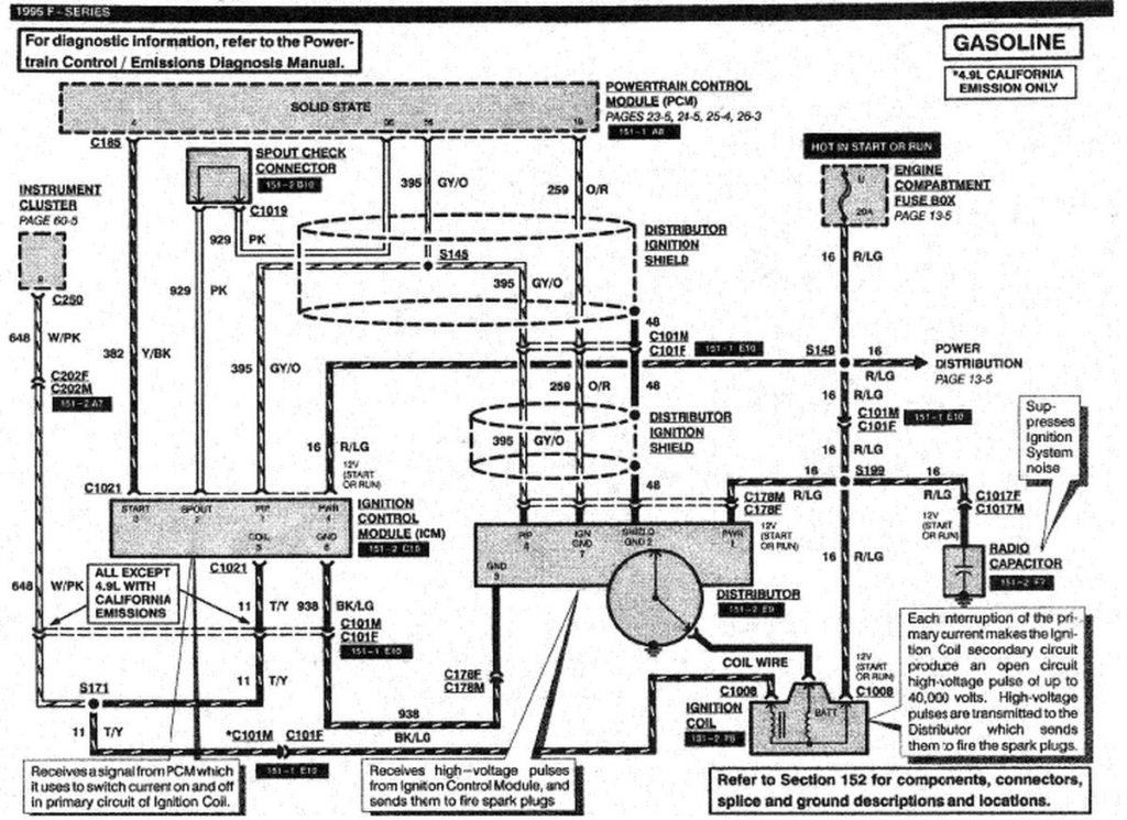
The terminology used to determine the kind and model of an ignition coil is the most important thing. The fundamental diagram of ignition wiring depicts various connections and terminals. There are two primary and secondary connections. Each coil operates at a specific voltage. The first step to determine the kind you have is to check the voltage of S1 or the primary terminal. To determine whether it’s an A, C, or B coil, you must also test S1’s resistance.
The chassis’ negative end should be connected to connect to the coil’s lower-tension end. This is what you find in the diagram of wiring. The high-tension part is a positive connection to the sparkplugs. To reduce the noise, the coil’s body metal must be connected to the chassis. This is not necessary for electrical use. A wiring diagram can also illustrate the connection between the positive and negative coils. In some cases scanning the local auto parts store can help you identify defective ignition coils.
The black-and-white-striped wire from the harness goes to the negative terminal. The white wire is the other one. It has a black trace on it, and connects to the positive terminal. The black wire connects to the contact breaker. You can examine the connections using a paperclip to pull the wires out of the housing. Make sure you don’t bend the connectors.
Accessory terminals
The wiring diagrams for the ignition show the different wires used to power the various components of the car. There are generally four color-coded terminals to each component. Accessories are red, the battery is yellow, and the starter solenoid is green. The “IGN” terminal lets you start your car, operate the wipers, and any other features that operate. The diagram illustrates how to connect ACC or ST terminals, and other.
The terminal BAT connects the battery to the charger. The electrical system will not start without the battery. Also, the switch won’t be able to turn on without the battery. You can refer to your wiring diagram if you’re not sure where the batteries of your car are. The accessory terminals on your car are connected to the battery as well as the ignition switch. The BAT Terminal is connected to the Battery.
Some ignition switches come with an accessory position. It allows users to connect their outputs to another location without the ignition. Sometimes, customers want to utilize an additional output that is not connected to the ignition. To allow the auxiliary output to be used, plug in the connector to the same shade as that of the ignition. Connect it to the ACC end of the switch. This feature of convenience is fantastic however, there’s one distinction. Many ignition switches have an ACC position when the car is in ACC mode and a START position when you are in IGN.
Gallery of 1990 F150 Ignition Switch Wiring Diagram
Gallery of 1990 F150 Ignition Switch Wiring Diagram


