1984 Johnson 25 Hp Outboard Ignition Wiring Diagram – Let’s start by looking at the different kinds of terminals that are found in an ignition switch. These terminals serve for the Ignition button, Coil and Accessory. After we’ve identified what these terminals are and what they do, we can then determine the various components in the ignition wiring. We will also cover the different functions of the Ignition Switch and the Coil. Then, we’ll focus to the accessory terminals.
Terminals for ignition switch
An ignition switch is comprised of three switches. They supply the battery’s voltage to different places. The ON/OFF state of the switch that controls the ignition is managed by the second switch, which supplies the choke with power when it’s pushed. Different manufacturers use their own color-coding systems for the different conductors, that is described in a separate article. OMC follows this system. A connector can be added to the ignition switch in order to connect the digital tachometer.
Although most ignition switch terminals are duplicated, the number may not be consistent with the diagram. To ensure that the wires are properly plugged in to the ignition switch you must verify their continuity. You can check this using a simple multimeter. When you’re satisfied that the wires are in good order then you can connect the new connector. The wiring loom in an ignition system switch that is supplied by the manufacturer differs.
You must first understand the ways in which the ACC outputs and the auxiliary outputs function to connect them. The ACC, IGN and START terminals are your default connection to the ignition switch. They also serve as the primary connections to your radio and stereo. The ignition switch is the engine’s on/off button. In older vehicles the ignition switch’s terminals are identified with the letters “ACC” as well as “ST” (for distinct magnetic wires).
Coil terminals
Understanding the terminology is the initial step in determining which type of ignition coil you have. In a basic ignition wiring diagram you’ll see several different connections and terminals, such as two primary and two secondary. The operating voltage of every coil is different. Therefore, it is crucial to test the voltage at S1 (primary terminal). S1 should also be checked for resistance in order to identify if the coil is a Type B, B, or an A coil.
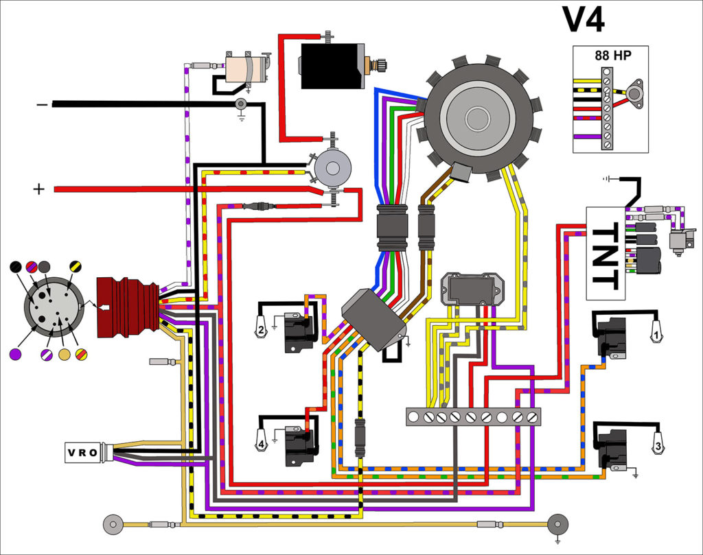
The low-tension coil side must be connected at the chassis’s minus. This is what you find in the wiring diagram. The high-tension part supplies the spark plugs with positive. For suppression purposes, the coil’s body metal is required to be connected to the chassis. This is not necessary to use electricity. A wiring diagram can depict the connection between positive and negative coils. Sometimes, an inspection at an auto parts store could detect a defective ignition wire.
The black-and-white-striped wire from the harness goes to the negative terminal. The white wire is the other one. It is black with a trace on it and it goes to the positive terminal. The black wire goes to the contact breaker. To check the connections, you can make use of a paperclip or pencil to pull them out of the plug housing. Be sure the terminals aren’t bent.
Accessory terminals
The wiring diagrams for the ignition show the different wires that power the various components of the car. There are generally four colors-coded terminus of each part. The red color is for accessories, yellow is the battery, and green for the starter solenoid. The “IGN terminal” is used to power the wipers and other operating features. The diagram shows the connections to the ACCas well as ST terminals.
The terminal BAT connects the battery to the charger. The electrical system cannot begin without the battery. Additionally, the switch won’t start. A wiring diagram can inform the location of the battery in your car. The accessory terminals in your vehicle are connected to the battery as well as the ignition switch. The BAT terminal is connected to the battery.
Some ignition switches have the “accessory” position that permits users to regulate their outputs without needing to turn on the ignition. Sometimes, customers wish to utilize the auxiliary output separately from the ignition. Use the auxiliary output by connecting the connector to the ACC terminal on the switch using the same colors. This feature of convenience is fantastic however there’s a differentiator. A majority of ignition switches feature the ACC position when your car is in ACC mode and a START mode when it is in IGN.
Gallery of 1984 Johnson 25 Hp Outboard Ignition Wiring Diagram
Gallery of 1984 Johnson 25 Hp Outboard Ignition Wiring Diagram


