Evinrude E-tec Ignition Switch Wiring Diagram – First, we will look at the different types of terminals that are found in the ignition switch. These terminals are used for the Ignition button, Coil and Accessory. Once we know what these terminals do and what they do, we can then determine the various components in the ignition wiring. We will also discuss the roles of the Ignition switch as well as the Coil. Following that, we’ll shift our attention to Accessory terminals.
The terminals are for ignition switches.
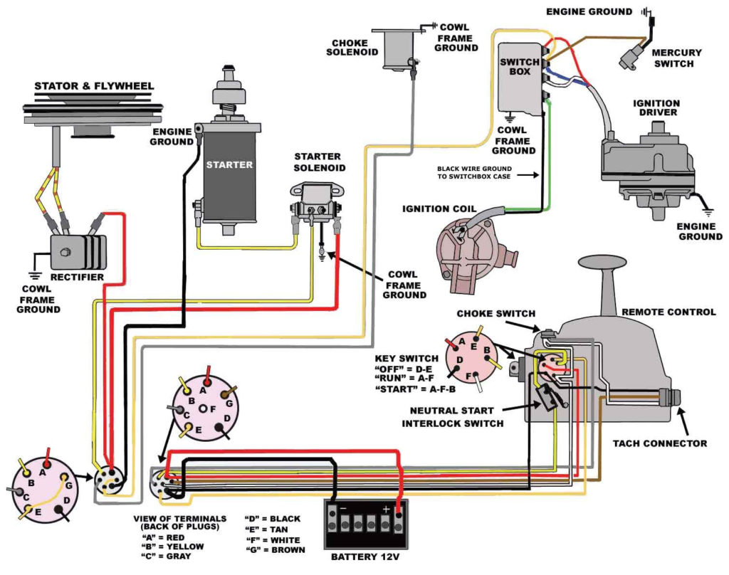
There are three separate switches in an ignition switch, which provide the battery’s voltage to several different places. The first switch provides the choke with power when pushed, and the second is the switch that controls the ignition’s ON/OFF positions. Each manufacturer has its unique color-coding system, which we will discuss in another article. OMC uses this method. The ignition switch comes with an adapter for the addition of the Tachometer.
Although many ignition switch terminals do not come in original form The numbering might not match the diagram. First, check the continuity of each wire to ensure that they are properly connected to the ignition switches. A multimeter that is inexpensive can aid in this. After you’re sure that the wires are running in good harmony and you are able to connect the new connector. The wiring loom used for an ignition switch that is supplied by the factory will be different from the one you have in your vehicle.
Before you can connect the ACC outputs to your car’s auxiliary outputs, it is important to understand the basics of these connections. The ACC and IGN terminals are the default connections on your ignition switch. the START and IGN terminals are the principal connections for the radio and stereo. The ignition switch’s function is to turn the car’s engines on and off. Older cars are equipped with ignition switch’s terminals that are labeled “ACC” or “ST” (for individual magnetowires).
Terminals for Coil
Understanding the terminology used is the initial step in finding out the right kind of ignition coil to choose. The diagram of the basic ignition wiring depicts various connections and terminals. There are two primary and secondary connections. Each coil is operating at a certain voltage. The first step in determining which kind of coil you’re dealing with is to test the voltage on S1, or the primary terminal. You should also check S1 for resistance in order to determine if it’s an A B, C, or coil.
The negative of the chassis must be connected to the side of low-tension. It is also the ground in an ignition wiring diagram. The high tension side provides positive power directly to the spark plugs. To prevent noise the coil’s metal body must be connected with the chassis. It’s not necessary for electrical use. You will also see the connections of the positive and the negative coil’s terminals on the diagram of the ignition wiring. You may find an issue with your ignition coil which can be identified by scanning it in an auto parts store.
The black-and-white-striped wire from the harness goes to the negative terminal. The white wire is black-colored and goes to the terminal opposite. The black wire connects to the contact breaker. You can take the black wire from the housing of the plug using a paper clip If you’re unsure of the connections. Make sure that the connectors do not bend.
Accessory terminals
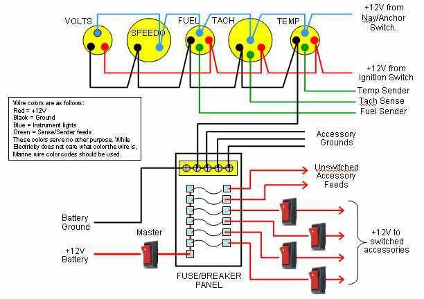
The diagrams for ignition wiring depict the wiring used to power the vehicle’s electrical supply. Typically there are four color-coded terminals for each component. Red refers to accessories, yellow the battery, and green for the starter solenoid. The “IGN” terminal can be utilized to turn on the car, operate the wipers, and other features. The diagram shows how to connect ACC or ST terminals, and other.
The terminal BAT is the connection for the battery. The electrical system will not start if the battery isn’t connected. Furthermore, the switch won’t start. It is possible to look up your wiring diagram to figure out where your car’s batteries are located. The ignition switch and battery are connected through the accessory terminals. The BAT terminal is connected to the battery.
Some ignition switches come with an additional “accessory position” that lets users alter their outputs without the ignition. Sometimes, a customer wants to make use of the auxiliary output separate from the ignition. It is possible to use the secondary input by connecting it to the ACC terminal. This is a useful feature, but there is an important difference. A majority of ignition switches feature an ACC position when your vehicle is in the ACC mode and a START mode when it is in IGN.
Gallery of Evinrude E-tec Ignition Switch Wiring Diagram
Gallery of Evinrude E-tec Ignition Switch Wiring Diagram


