1985 Ford F150 Ignition Wiring Diagram – Let’s start by looking at the different types terminals found on an ignition switch. The terminals are the Ignition switch and Coil along with the Accessory. Once we have established what these types of terminals are, we will proceed to discover the various components of the 1985 Ford F150 Ignition Wiring Diagram. We will also discuss the functions for the Ignition switch, as well as the Coil. Then we’ll move on to the Accessory Terminals.
Terminals for ignition switches
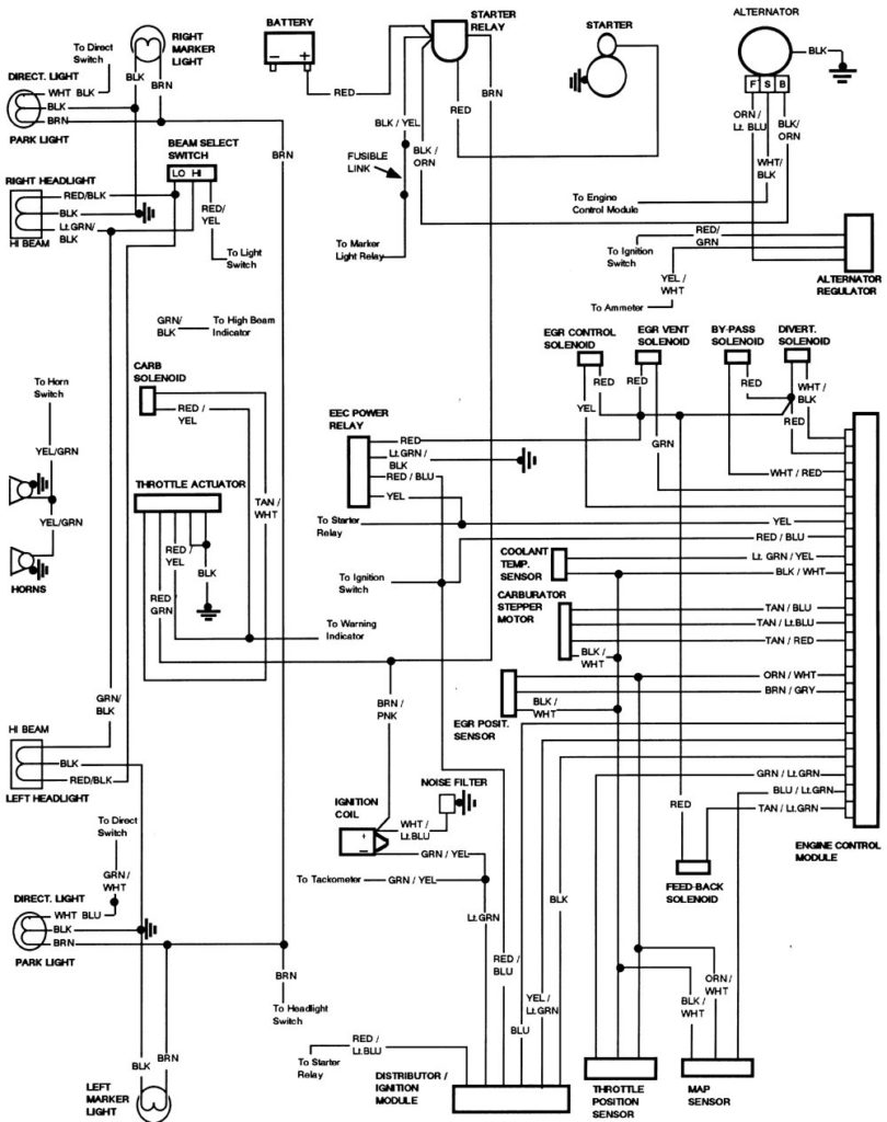
An ignition switch has three switches that supply the battery’s power to various destinations. The first switch is used to drive the choke by pushing it. Then, the second is for the ON/OFF setting. Different manufacturers employ various color codes for the different conductors. This is discussed in a separate article. OMC utilizes the same system. This connector allows the connection of a speedometer to the ignition switch.
While many ignition switch terminals may not be original, the numbering of each may not be in line with the diagram. Verify the integrity of the wires first to ensure that they’re properly connected to the ignition switch. This can be done using an inexpensive multimeter. After you’re sure that all wires are in good order then you can connect the new connector. If your vehicle has an ignition switch that is installed, the wiring diagram will differ.
It is important to understand how the ACC outputs and the auxiliary outputs work in order to connect them. The ACC terminals and IGN terminals are the standard connections for the ignition switch. The START and IGN connections are the primary connections for radio and stereo. The ignition switch is responsible for turning the car’s engine on and off. The terminals on older cars ignition switches are marked by “ACC” and ST (for individual magneto wires).
Terminals for coil
Understanding the terminology used is the first step in determining what type of ignition coil. You’ll see a number of connections and terminals in an ignition wiring schematic, including two primary, as well as two secondary. The voltage that operates on each coil is different. This is why it is important to first test the voltage at S1 (primary terminal). S1 should also be checked for resistance to determine if it’s a Type B, B, or an A coil.
The negative end of the chassis end should be connected to connect the coil’s low-tension end. This is what’s called the ground in the wiring diagram for ignition. The high-tension component provides the spark plugs with positive. It is required to suppress the coil’s metallic body be connected to its chassis, but not essential. The wiring diagram of the ignition will explain how to connect the two terminals of the positive or negative coils. In some instances you’ll discover that the ignition coil is damaged and can be diagnosed with a scan at an auto parts shop.
The black-and-white-striped wire from the harness goes to the negative terminal. The positive terminal also receives a second white wire, which has a black trace. The black wire connects to the contactbreaker. To verify the connection, make use of a paperclip or pencil to lift them out from the plug housing. Make sure the terminals aren’t bent.
Accessory terminals
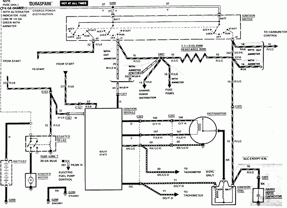
The diagrams for ignition wiring show the wires that are used in the vehicle’s power supply. Typically, there are four different colors-coded terminals that are used for each component. To identify accessories, red stands for starter solenoid, yellow is for battery and blue for accessory. The “IGN” terminal can be used to start the car , and also to operate the wipers and other operating functions. This diagram shows how to connect ACC and ST terminals with the rest of components.
The terminal BAT connects the battery to the charger. The electrical system will not start without the battery. The switch also won’t start without the battery. It is possible to view your wiring diagram to determine the location of your car’s batteries. situated. The accessory terminals on your car are connected to the battery and the ignition switch. The BAT connector is connected to your battery.
Certain ignition switches have an accessory position. It allows users to connect their outputs to a different place without having to turn on the ignition. Some customers might want to utilize the auxiliary input separately from the ignition. To use the auxiliary output, wire the connector in the same colors as ignition, and connect it to the ACC terminal on the switch. This convenience feature is great however, there’s one differentiator. Most ignition switches will be in an ACC position if the car is in ACC however, they’ll be in the START position if the vehicle is IGN.
Gallery of 1985 Ford F150 Ignition Wiring Diagram
Gallery of 1985 Ford F150 Ignition Wiring Diagram


