Nissan Hardbody Ignition Wiring Diagram – We will first look at the various kinds and functions of terminals on the ignition switches. These are the terminals that connect the Ignition, Coil, or Accessory. Once we know the purpose of these terminals then we can be able to identify the various parts of the ignition wiring. We will also cover the different functions of the Ignition Switch and the Coil. We will then discuss the function of the Ignition switch and Coil.
The terminals are for ignition switches.
Three switches can be found on an ignition switch. Each of these switches is able to feed the battery’s voltage to various locations. The ON/OFF position of the switch that controls the ignition is managed by the second switch, which delivers the choke with power when it’s pulled. Different manufacturers use different color-coding systems that correspond to the conductors. OMC follows the same system. The ignition switch comes with an adapter for the addition of a Tachometer.
While many ignition switch terminals may not be authentic, the numbering of each may not match the diagram. To make sure that the wires are correctly plugged in to the ignition switch you must verify their continuity. This can be done with a multimeter that is inexpensive. After you’re happy with the continuity of the wires, you can install the new connector. The wiring loom for an ignition switch that’s factory-supplied will be different than the one in your car.
To connect the ACC outputs to the auxiliary outputs on your vehicle, you have to understand how these two connections work. The ACC terminals and IGN terminals function as the standard connections for your ignition switch. The START and IGN connections are the primary connections for radio and stereo. The ignition switch regulates the engine in your car. In older vehicles the ignition switch’s terminals are identified with the initials “ACC”, and “ST” (for distinct magnetic wires).
Terminals for coil
Understanding the terms utilized is the initial step in determining the kind of ignition coil to choose. The basic ignition wiring diagram shows a number different connections and terminals. There are two primary and one secondary. The coils are equipped with a particular operating voltage. The first step in determining which type you’ve got is to check the voltage on S1, the main terminal. To determine whether it’s an A, C or B coil you should also test the resistance on S1’s.
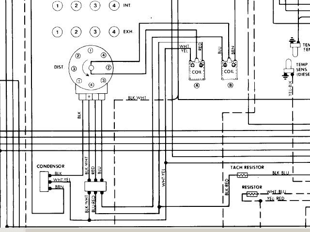
The low-tension side of the coil must be connected to the chassis”negative. This is what is known as the ground for the ignition wiring. The high-tension side delivers the positive power directly to the spark plugs. The coil’s metal body needs to connect to the chassis for suppression purposes, but it is not electrically required. The diagram of the ignition wiring will also show the connections of the positive coil’s terminals. In certain instances scanning the local auto parts store can help you identify malfunctioning ignition coils.
The black-and-white-striped wire from the harness goes to the negative terminal. The positive terminal receives the white wire with a black trace. The black wire connects to the contact breaker. To check the connections, make use of a paperclip or pencil to lift them out from the plug housing. Also, make sure to verify that the connections haven’t been bent.
Accessory Terminals
The wiring diagrams for the ignition show the different wires used to are used to power various components of the car. Each part has four distinct connections that are color coded. The red symbol represents accessories, yellow for the battery and green is for the solenoid for starters. The “IGN” terminal can be utilized to turn on the car, turn on the wipers and other features. This diagram demonstrates how to connect ACC and ST terminals with the rest of components.
The battery is connected to the terminal called BAT. The electrical system won’t start when the battery isn’t connected. The switch won’t turn on if the battery isn’t present. You can refer to your wiring diagram if not sure where the batteries of your car are located. The accessory terminals in your vehicle connect to the battery as well as the ignition switch. The BAT terminal is connected with the battery.
Certain ignition switches come with the “accessory” setting that allows users to regulate their outputs without having to use the ignition. Some customers might want to use the auxiliary input separately from the ignition. You can use the auxiliary input by connecting it to the ACC terminal. Although this is a fantastic feature, there’s one thing to be aware of. Most ignition switches will be in an ACC position when the vehicle is in ACC however, they’ll be in the START position if the vehicle is in IGN.
Gallery of Nissan Hardbody Ignition Wiring Diagram

Gallery of Nissan Hardbody Ignition Wiring Diagram


