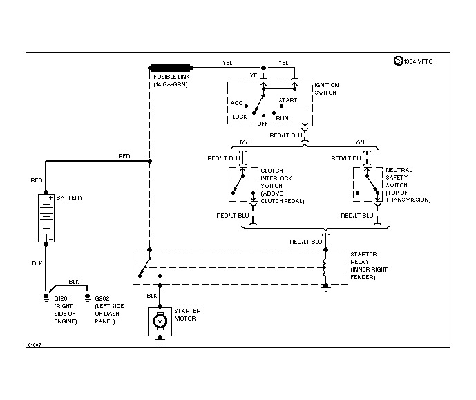
1987 Ford F150 Ignition Wiring Diagram – We will first look at the various types and purposes of the terminals in the ignition switches. The terminals are the Ignition switch and Coil along with the Accessory. Once we’ve established the purpose of the terminals it is possible to determine the various components of the ignition wiring. Then, we will discuss the roles of the Ignition switch as well as the Coil. Following that, we will proceed to the Accessory Terminals.
Terminals for ignition switch
An ignition switch is made up of three switches. They are responsible for supplying the battery’s energy to various destinations. The first switch supplies the choke with power when it is pushed. The third is the switch that controls the ignition’s ON/OFF positions. Different manufacturers use different color codes for various conductors. This is described in a different article. OMC utilizes the same system. A tachometer adapter is installed on the ignition switch, allowing for the addition of the Tachometer.
Although the majority of ignition switch terminals may not be original, the numbers for each one may not be in line with the diagram. To ensure that the wires are correctly connected to the switch you should check their continuity. This can be accomplished with a multimeter that is inexpensive. Once you’re satisfied with the connection, you can place the new connector. The wiring loom of the ignition switch supplied by the factory will be different from the one you have in your car.
Before connecting the ACC outputs to the auxiliary outputs of your car, it is important to know the fundamentals of these connections. The ACC and IGN connectors are the standard connections of the ignition switch. The START, IGN, and ACC terminals are the main connections for radios or stereo, the START/IGN connections are the primary ones. The ignition switch turns the car’s engine ON and OFF. The ignition switch terminals on older vehicles are marked with the letters “ACC” as well as “ST” (for the individual magneto wires).
Terminals for Coil
To identify the kind of ignition coil, the first step is to understand the definition of. An ignition wiring diagram will display a range of terminals and connections, including two primary and two secondary. Each coil is equipped with a distinct operating voltage. To determine which type of coil you’ve got the first step is to test the voltage at S1, which is the primary terminal. S1 should also be checked for resistance in order to identify whether it’s an A, Type B or an A coil.
The low-tension end of the coil needs to be connected to the chassis the negative. This is the ground in the diagram of the ignition wiring. The high-tension part provides positive direct to the sparkplugs. The body of the coil has to be connected to the chassis to suppress the effect, but it is not electrically necessary. You will also see the connections of the positive and the negative coil’s terminals on the ignition wiring diagram. Sometimes, a visit to an auto part store can identify a problem with the ignition wire.
The black-and-white-striped wire from the harness goes to the negative terminal. The terminal for the negative is served by the trace in black that’s joined to the white wire. The contact breaker is attached to the black wire. To test the wires’ connections, use a paperclip and lift them out of the housing. It’s also essential to make sure the terminals do not bend.
Accessory Terminals
Ignition wiring diagrams depict the various wires utilized to power the different components. There are usually four different colors of terminals connected to each part. The red color is for accessories, yellow is the battery, and green the starter solenoid. The “IGN terminal” is used to provide power to the wipers and other operating features. This diagram demonstrates how to connect ACC and ST terminals with the rest of the components.
The terminal BAT is the connection to the battery. The electrical system can’t be started without the battery. In addition the switch isn’t turned on. The wiring diagram will inform you where to find your car’s battery. The accessory terminals on your vehicle connect to the battery as well as the ignition switch. The BAT terminal is connected with the battery.
Certain ignition switches have a separate “accessory” position, where users can control their outputs with no ignition. Sometimes, a customer wants to utilize the auxiliary output separately from the ignition. You can use the auxiliary input by connecting it to the ACC terminal. Although this is a useful option, there’s an significant difference. The majority of ignition switches are set to operate in the ACC position when the vehicle is in the ACC position, whereas they’re set to the START position when the vehicle is in the IGN position.
Gallery of 1987 Ford F150 Ignition Wiring Diagram
Gallery of 1987 Ford F150 Ignition Wiring Diagram


