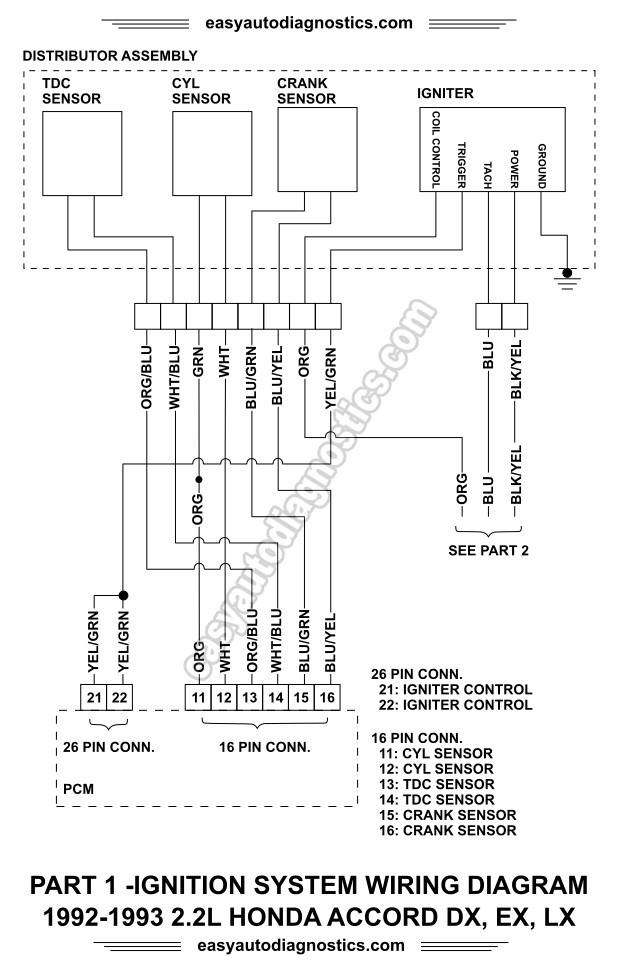
1993 Honda Accord Ignition Wiring Diagram – Let’s first examine the various terminals that are used in the ignition switch. These terminals are used for the Ignition button, Coil and Accessory. Once we know the purpose of these terminals are used for, we will proceed to determine the various parts of the 1993 Honda Accord Ignition Wiring Diagram. We’ll also discuss the functions of the Ignition switch and Coil. After that we will proceed to the Accessory Terminals.
Terminals for ignition switches
An ignition switch contains three separate switches that feed the battery’s current to different destinations. The ON/OFF state of the switch that controls the ignition is managed by the first switch, which delivers power to the choke whenever it’s pushed. Different manufacturers use their own color-coding systems for the different conductors, that is described in a separate article. OMC follows this approach. This connector allows the attachment of a speedometer the ignition switch.
While the majority of the ignition switch terminals are not original, the numbers for each might not be consistent with the diagram. You should first check the electrical continuity to ensure that they are plugged into the correct ignition switch. A cheap multimeter can assist you in this. After you’re sure that the wires are running in good harmony then you can connect the new connector. If your car has an installed ignition switch the wiring diagram may differ.
To connect the ACC outputs to the auxiliary outputs on your car, you’ll need to understand how these two connections work. The ACC and IGN connectors are the default connections of your ignition switch. While the START, IGN, and ACC terminals are primary connections for the radio or stereo, the START/IGN connections are the main ones. The ignition switch regulates the engine in your car. The terminals of older cars ignition switches are marked by “ACC” and ST (for the individual magneto wires).
Terminals for coil
Understanding the terms is the first step in knowing what type of ignition coil you own. A simple diagram of the wiring will reveal a variety of connections and terminals, including two primary and two secondaries. The coils come with a distinct operating voltage. The initial step in determining which type you’re using is to test the voltage at S1, the main terminal. To determine if it is a Type A, C or B coil, it is recommended to also test the resistance on S1’s.
The low-tension end of the coil should be connected to the chassis”negative. This is what’s called the ground in the diagram of the ignition wiring. The high-tension part provides positive direct to the sparkplugs. The aluminum body of the coil has to be linked to the chassis for suppression but isn’t required. The wiring diagram of the ignition will demonstrate how to connect the two terminals of the positive and negative coils. Sometimes, a malfunctioning ignition coil can be detected by a scan done in an auto parts shop.
The black-and-white-striped wire from the harness goes to the negative terminal. The positive terminal receives the white wire with the trace of black. The black wire goes to the contact breaker. To check the connection, employ a paperclip, or a pencil to lift them out of the housing for the plug. Be sure that the terminals aren’t bent.
Accessory terminals
Diagrams of the ignition wiring show the wires that power various parts of the car. There are generally four colors-coded terminus of each part. Red refers to accessories, yellow is the battery, and green the starter solenoid. The “IGN terminal is used for starting the vehicle, controlling the wipers and various other functions. The following diagram shows how to connect both the ACC terminal as well as the ST terminals to various components.
The battery is connected to the terminal whose name is BAT. The electrical system can’t begin without the battery. Additionally, the switch will not be able to turn on without the battery. A wiring diagram can tell you where to find the battery in your car. Your car’s accessory terminals connect to the ignition switch and the battery. The BAT Terminal is connected to the battery.
Certain ignition switches provide the option of an “accessory position” that lets users alter their outputs without the ignition. Customers may want to utilize the auxiliary output in addition to the ignition. The auxiliary output is utilized to connect the connector with the same color as your ignition and attaching it to the ACC terminal of the switch. This is a great convenience feature however there’s a difference. The majority of ignition switches have an ACC position when the vehicle is in ACC however they’ll be at the START position when the vehicle is IGN.
Gallery of 1993 Honda Accord Ignition Wiring Diagram
Gallery of 1993 Honda Accord Ignition Wiring Diagram


