Harley 3 Pole Ignition Switch Wiring Diagram – The first step is to take a look at the different types of terminals that are used in the ignition switch. These include the terminals that are for the Ignition switch, Coil, and Accessory. Once we have identified what these terminals do then we can determine the various components in the ignition wiring. In addition, we will discuss the different functions of the Ignition Switch and the Coil. Then, we’ll turn our attention to the Accessory terminals.
Terminals for the ignition switch
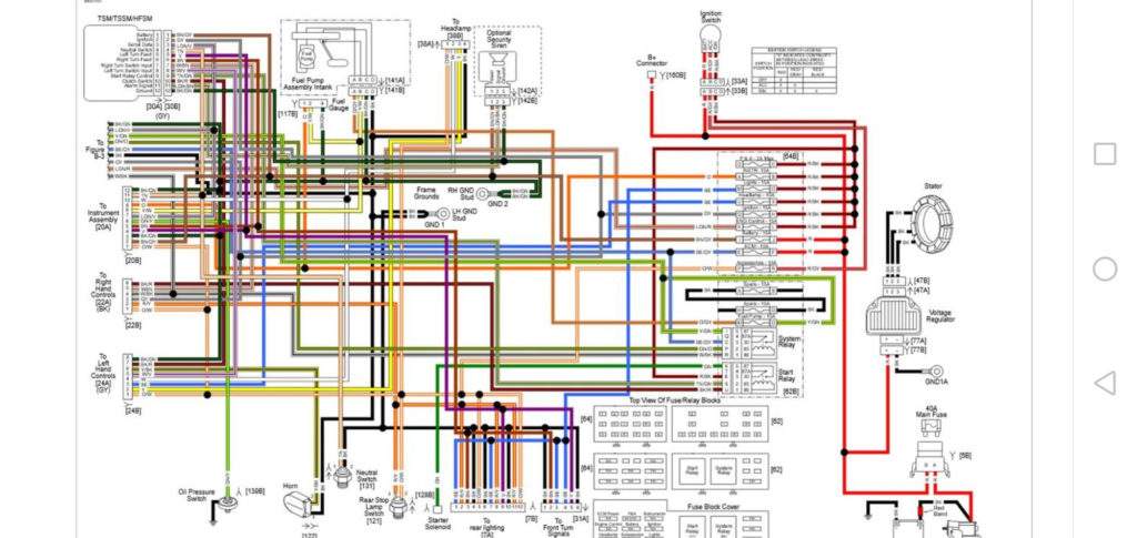
There are three switches in an ignition switch that provide the battery’s voltage to a variety of locations. The ON/OFF position of the ignition switch is controlled by the first switch, which provides power to the choke when it’s pushed. Different manufacturers have distinct color-coding systems that correspond to the conductors. OMC utilizes this system. There is a connector in the ignition switch to allow attaching a Tachometer.
Although some ignition switch terminals could not be authentic, the numbering of each may not match the diagram. You should first check the integrity of the wires to ensure that they are plugged into the ignition switch in the correct way. A multimeter is a great tool to check the continuity. After you have verified the continuity of the wires you can then install the connector. If you are using a factory-supplied ignition switch the wiring loom will be different from that you have in your car.
To connect the ACC outputs to the auxiliary outputs of your car, you need to first understand the way these two connections function. The ACC and IGN connectors are the standard connections for your ignition switch. The START, IGN, and ACC terminals are the primary connections to the radio or stereo, the START/IGN terminals are the primary ones. The ignition switch is responsible for turning the car’s engine on and off. Older cars are identified by the initials “ACC”, “ST”, (for individual magneto cables) on their ignition switch’s terminals.
Terminals for coil
Understanding the terminology that is used is the first step to finding out the right kind of ignition coil to choose. You’ll see a number of connections and terminals within a basic ignition wiring schematic which includes two primary and two secondary. Each coil is equipped with a distinct operating voltage. To determine which type of coil you’ve got first, you need to check the voltage at S1, which is the primary terminal. S1 must also go through resistance testing to determine if it are an A or B coil.
The negative of the chassis must be connected to the side of low-tension. This is also the ground in the wiring diagram for ignition. The high tension part supplies positive directly the spark plugs. The aluminum body of the coil has to be linked to the chassis for suppression, but it isn’t electrically required. The wiring diagram of the ignition will explain how to connect the terminals of either the negative or positive coils. It is possible to find an issue with your ignition coil that can be easily diagnosed by looking it up at an auto parts store.
The black-and-white-striped wire from the harness goes to the negative terminal. Positive terminal gets the second white wire, which is black in its trace. The contact breaker is attached to the black wire. If you’re not certain about the connections of both, you can use the clip of a paperclip to remove them from the plug housing. Be sure that the terminals aren’t bent.
Accessory terminals
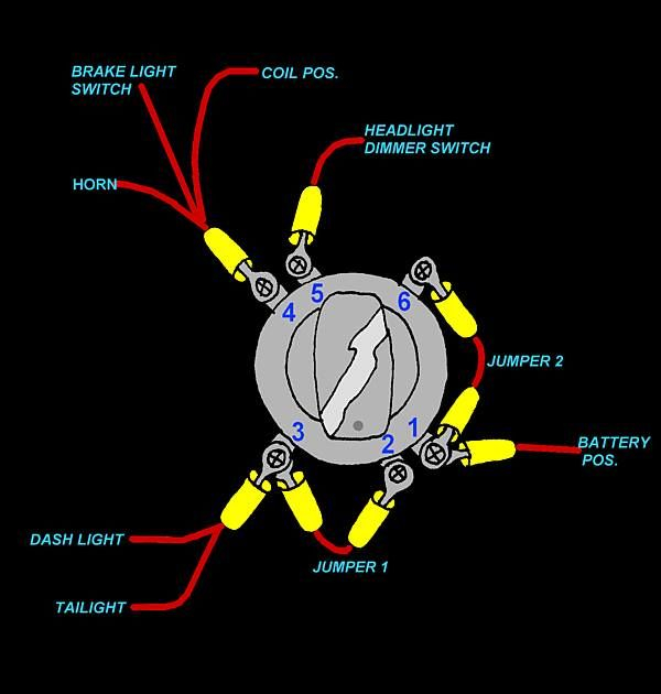
Diagrams of ignition wiring show the wires that are used in the power supply of the vehicle. Each part has four distinct connections that are color coded. Red refers to accessories, yellow the battery, and green the starter solenoid. The “IGN terminal” is used to provide power to the wipers and other operating functions. The diagram illustrates the connection to the ACCas well as ST terminals.
The terminal BAT is where the battery is. The electrical system won’t start in the event that the battery isn’t connected. Also, the switch won’t start without the battery. It is possible to look up your wiring diagram to figure out where the batteries of your car are located. The accessory terminals in your car are connected with the battery and the ignition button. The BAT terminal is connected to the battery.
Some ignition switches have an “accessory” position that permits users to control their outputs , without having to use the ignition. Sometimes, customers may wish to utilize the auxiliary output separately from the ignition. Use the auxiliary output by connecting the connector to the ACC terminal on the switch with the same colors. This is a great option, but there’s one important distinction. Most ignition switches are designed to show an ACC status when the car is in either the ACC or START positions.
Gallery of Harley 3 Pole Ignition Switch Wiring Diagram
Gallery of Harley 3 Pole Ignition Switch Wiring Diagram


