Jk290a Ignition Switch Wiring Diagram – First, we will examine the various types of terminals that are found in the ignition switch. They include terminals for the Ignition switch, Coil, and Accessory. Once we understand the function of each terminal, we are able to determine the components of the ignition wiring. We will also cover the roles of both the Ignition Switch and Coil. Next, we’ll discuss the roles of the ignition switch and Coil.
Ignition switch terminals
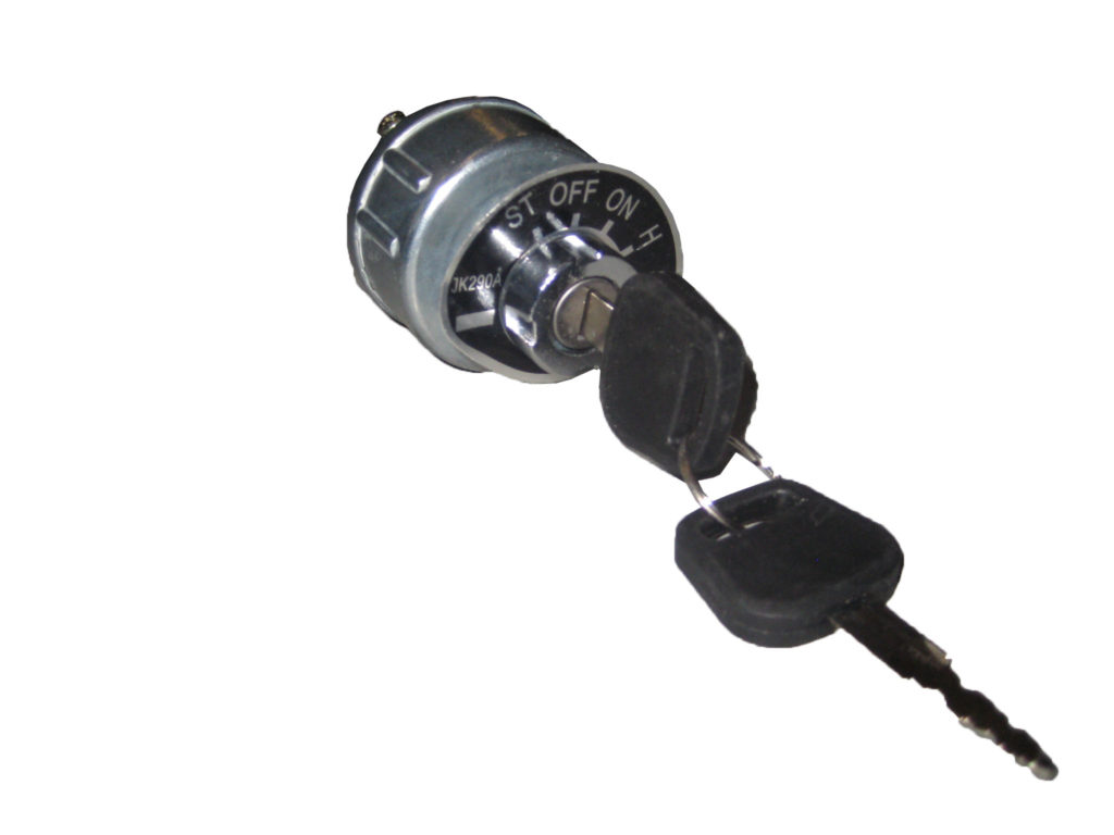
The ignition switch consists of three different switches. These are responsible for feeding the battery’s energy to various locations. The first switch supplies power to the choke when it is pushed. The third is the switch that controls the ignition’s ON/OFF positions. Different manufacturers employ various color codes for the various conductors. This is discussed in a separate article. OMC follows the same system. Connectors can be attached to the ignition switch to include a digital Tachometer.
Although some ignition switch terminals don’t have the original design, the numbering may not be in line with the diagram. Check the electrical continuity first to ensure that they’re connected correctly to the ignition switch. A multimeter that is inexpensive can assist you in this. Once you are satisfied that the wires are in good order then you can connect the new connector. If you have a factory-supplied ignition switch the wiring loom will be distinct from the one that is in your car.
It is important to know the differences between the ACC and the auxiliary outputs. The ACC and IGN terminals are the default connections for your ignition switch. the START and IGN terminals are the primary connections for radio and stereo. The ignition switch’s function is for turning the car’s engine on and off. Older cars are identified by the letters “ACC”, “ST”, (for individual magneto cables) on their ignition switch’s terminals.
Terminals for coil
Understanding the terminology is the first step towards determining which type of ignition coil you have. A basic diagram of the wiring will provide you with a range of connections and terminals. Each coil comes with its own operating voltage. To determine the type of coil you own the first step is to check the voltage at S1, which is the primary terminal. S1 must be tested for resistance in order to identify if the coil is type A, B and/or C.
The low-tension side of the coil needs to be connected to the chassis’ negative. This is the ground in the wiring diagram for ignition. The high tension side supplies positive directly the spark plugs. It is necessary for the purpose of suppression that the coil’s metallic body be connected to its chassis however it isn’t essential. The wiring diagram of the ignition will demonstrate how to connect the two terminals of the positive and negative coils. Sometimes, a check at an auto parts shop can identify a problem with the ignition wire.
The black-and-white-striped wire from the harness goes to the negative terminal. The positive terminal receives the white wire with the trace of black. The black wire connects to the contactbreaker. If you’re unsure of the connections between the twowires, use the clip of a paperclip to remove them from the plug housing. Make sure you check that the terminals have not been bent.
Accessory terminals
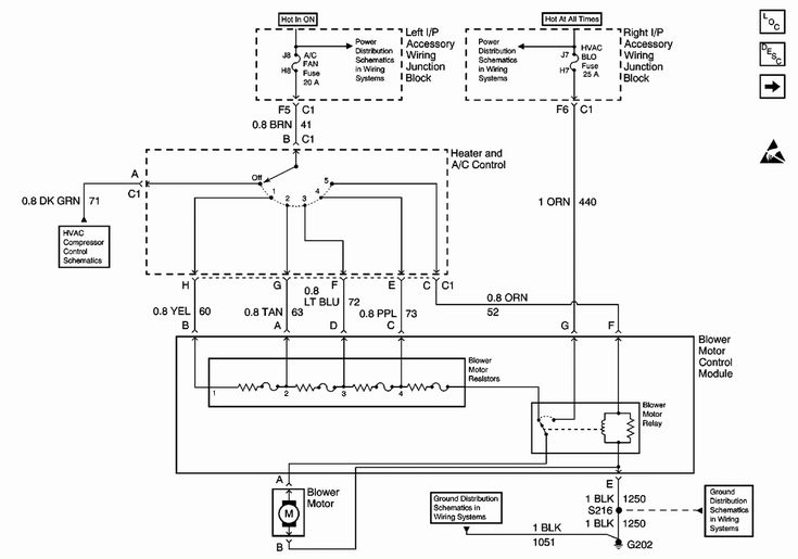
Diagrams of ignition wiring show the different wires used to power the various components. There are usually four different colored terminals for each component. The red color is used for accessories while yellow is the battery, while green is the starter solenoid. The “IGN” terminal is used to start the car and operate the wipers, as well as other operating features. The diagram illustrates the connection to the ACCas well as ST terminals.
The terminal known as BAT is the location where the battery is. The electrical system cannot start without the battery. Furthermore the switch isn’t turned on. The wiring diagram will tell the location of your car’s battery. The accessory terminals of your vehicle are connected to the battery as well as the ignition switch. The BAT terminal is connected to the battery.
Some ignition switches come with an additional “accessory position” that lets users adjust their outputs independently of the ignition. Sometimes, customers may wish to use the auxiliary output separately from the ignition. In order to use the auxiliary output, connect the connector with identical colors to the ignition, connecting it to the ACC terminal on the switch. This is a convenient feature however, it does have one key differentiator. Most ignition switches are designed to show an ACC status when the car is at the ACC or START positions.
Gallery of Jk290a Ignition Switch Wiring Diagram
Gallery of Jk290a Ignition Switch Wiring Diagram


