Chrysler Ignition Module Wiring Diagram – The first step is to look at the different terminals on the ignition switch. These include the terminals for the Ignition switch, Coil, and Accessory. Once we’ve determined the function of these terminals, we can recognize the various parts of the ignition wiring. We will also discuss the roles of the Ignition switch and Coil. Following that, we will move on to the Accessory Terminals.
Terminals for ignition switches

There are three separate switches on the ignition switch, and they feed the battery’s voltage to a variety of destinations. The ON/OFF setting of the ignition switch is controlled by the third switch, which supplies power to the choke when it’s pushed. Each manufacturer has their unique color-coding system, which we’ll go over in a separate article. OMC follows the same system. Connectors can be attached to the ignition switch in order to include the digital tachometer.
While many ignition switch terminals could not be authentic, the numbering of each may not be in line with the diagram. Examine the electrical continuity first to make sure they are correctly plugged in the ignition switch. This can be accomplished using an inexpensive multimeter. After you’ve confirmed that the wires are in good condition, you can then connect the connector. The wiring loom for an ignition switch that is factory-supplied will be different than the one that you have in your car.
It is important to understand the ways in which the ACC outputs and auxiliary outputs function in order to connect them. The ACC and IGN terminals are the default connection on your ignition switch. the START and IGN terminals are the main connections for the radio and stereo. The ignition switch is the engine’s switch to turn off or on. Older cars are identified with the initials “ACC”, “ST”, (for individual magneto cables) on their ignition switch’s terminals.
Terminals for coil
The first step to determine the kind of ignition coil is to understand the terms employed. The fundamental diagram of ignition wiring depicts various connections and terminals. There are two primary and secondary connections. Each coil operates at a specific voltage. The first step to determine the kind of coil you’re using is to examine the voltage on S1, or the primary terminal. Also, you should check S1 for resistance to identify if it’s an A B, C, or coil.
The coil’s low-tension end must be connected with the chassis’ positive. This is also the ground on the diagram of ignition wiring. The high-tension side delivers positive directly to the spark plugs. To prevent noise the body of the coil must be connected to the chassis. But, it’s not necessary to connect the coil electrically. The ignition wiring diagram will also show you the connections between the negative and positive coil terminals. There could be an issue with your ignition coil which can be identified by scanning it at the auto parts shop.
The black-and-white-striped wire from the harness goes to the negative terminal. The white wire also is black with a trace on it, and it goes to the positive terminal. The black wire connects to the contactbreaker. It is possible to check the connections with a paperclip to pull the wires out of the housing. It’s also essential to make sure the terminals do not bend.
Accessory terminals
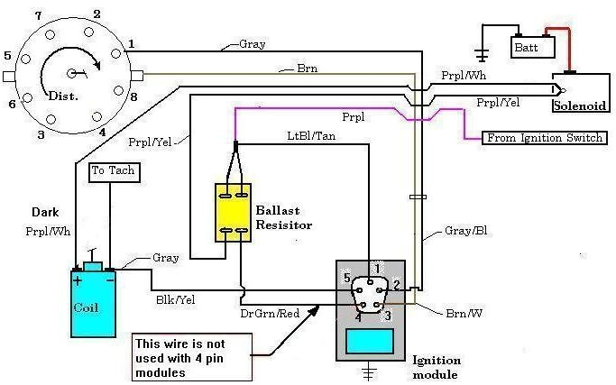
Diagrams of ignition wiring show the wiring used to provide power to various components of the car. There are typically four colored terminals for each component. The red symbol represents accessories, yellow for the battery and green is for the starter solenoid. The “IGN” terminal is utilized to turn on the car, turn on the wipers, as well as other functions. The diagram below shows how to connect the ACC terminal and ST terminals to other components.
The terminal BAT is where the battery is. The battery is vital to allow the electrical system to begin. A dead battery can cause the switch to stop turning on. To find the battery in your car look over your wiring diagram. The ignition switch and battery are connected through the accessory terminals. The BAT terminal is connected to the battery.
Certain ignition switches provide the option of an “accessory position” that allows users to alter their outputs without the ignition. Sometimes, users want to make use of an additional output independent of the ignition. It is possible to use the additional input by connecting the connector to the ACC terminal. This is an excellent feature, however there’s one important difference. Most ignition switches are set to be in an ACC position when the car is in the ACC position, while they’re set to the START position when the car is in the IGN position.
Gallery of Chrysler Ignition Module Wiring Diagram
Gallery of Chrysler Ignition Module Wiring Diagram


