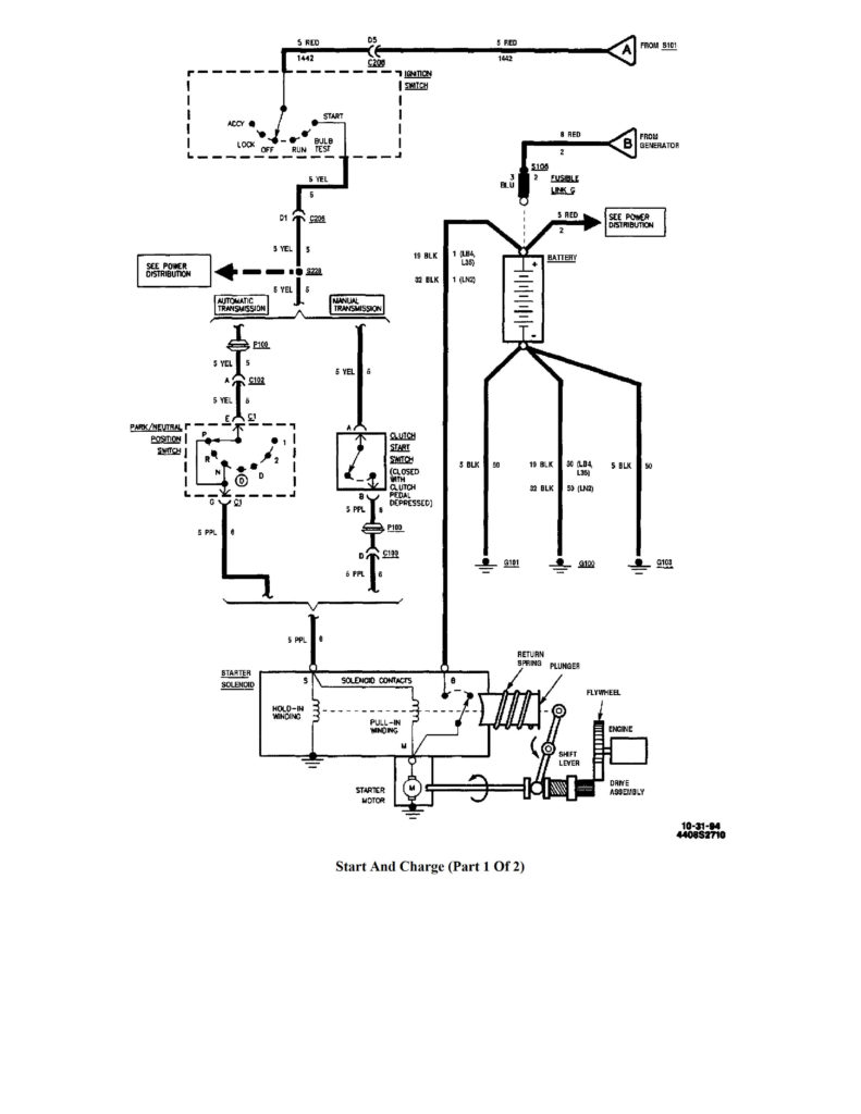
1995 Chevy S10 Ignition Wiring Diagram – Let’s begin by examining the different kinds and functions of terminals found on the ignition switches. These are the terminals for the Ignition, Coil, or Accessory. Once we know what these kinds of terminals are We will then determine the various parts of the 1995 Chevy S10 Ignition Wiring Diagram. We’ll also discuss the different functions of the Ignition Switch and Coil. After that we will discuss the Accessory Terminals.
Terminals for the ignition switch
The ignition switch consists of three different switches. These are responsible for supplying the battery’s power to several places. The first is used to drive the choke by pushing it. Then, the second is for the ON/OFF position. Different manufacturers employ different color codes for various conductors. This is described in another article. OMC uses the same method. The ignition switch comes with an adapter for the addition of an timer.
Although some ignition switch terminals don’t come in original form The numbering might not match that of the diagram. Check the continuity of the wires to ensure that they are connected to the ignition switch in the correct way. This can be checked with a simple multimeter. Once you’re satisfied with the connection, you can place the new connector. The wiring loom used in a factory-supplied ignition system switch differs.
It is essential to know the ways in which the ACC outputs and auxiliary outputs work in order to connect them. The ACC, IGN and START terminals are your default connection to the ignition switch. They also serve as the main connections to the radio and stereo. The ignition switch is the one that turns the car’s engine to and off. On older vehicles the terminals of the ignition switch are marked with the letters “ACC” and “ST” (for distinct magnet wires).
Terminals for coil
The language used to decide the type and model of the ignition coil is the primary thing. A basic ignition wiring layout will show you a number of connections and terminals. The coils have a specific operating voltage. The initial step in determining which type you’ve got is to check the voltage at S1, the main terminal. To determine if it is an A, C or B coil, you must also test S1’s resistance.
The chassis’ negative end should be connected to the coil’s low-tension side. This is what is known as the ground for the ignition wiring. The high-tension supply provides positive directly to spark plugs. It is required to suppress the coil’s metallic body be connected to the chassis, however, it is not necessary. The diagram of the ignition wiring will also demonstrate the connection of the negative and positive coil terminals. It is possible to find an issue with the ignition coil that can be easily diagnosed by scanning it in an auto parts retailer.
The black-and-white-striped wire from the harness goes to the negative terminal. Positive terminal gets the white wire that is black in its trace. The black wire connects to the contactbreaker. To check the connection, make use of a paperclip or pencil to lift them out of the plug housing. It’s also essential to ensure that the terminals don’t bend.
Accessory terminals
Diagrams of ignition wiring illustrate the wires that supply power to different parts of the car. Typically, there are four different color-coded terminals for each component. The red color is used for accessories and yellow is for the battery, while green is for the starter solenoid. The “IGN terminal is used for starting the car, controlling the wipers and other functions. This diagram shows how to connect ACC and ST terminals with the rest of components.
The terminal BAT is where the battery is. The electrical system won’t start in the event that the battery isn’t connected. Additionally, the switch won’t start. It is possible to refer to your wiring diagram if you are uncertain about where the car’s batteries are located. The ignition switch as well as the battery are connected by the accessory terminals. The BAT terminal is connected to the battery.
Some ignition switches feature the “accessory” setting that permits users to regulate their outputs without having to use the ignition. Customers sometimes want the auxiliary output to be used independently from the ignition. The auxiliary output could be used to connect the connector in the same colors as the ignition and connecting it to the ACC terminal of the switch. This option is useful, but it has one key difference. Most ignition switches are configured to be in an ACC position when the vehicle is in the ACC position, while they’re set to the START position when the car is in the IGN position.
Gallery of 1995 Chevy S10 Ignition Wiring Diagram
Gallery of 1995 Chevy S10 Ignition Wiring Diagram


