Dyna 2000 Ignition Wiring Diagram – First, we will take a look at the different kinds of terminals for the ignition switch. These terminals are for the Ignition button, Coil and Accessory. After we’ve identified the purpose of the terminals we will be able to recognize the various parts of the ignition wiring. In addition, we will discuss the different functions of the Ignition Switch and Coil. We’ll then turn our attention on the accessory terminals.
Terminals for ignition switch
An ignition switch has three switches. They supply the battery’s voltage to many different locations. The first is utilized to drive the choke by pushing it, and the third switch is used to control the ON/OFF position. Every manufacturer has its unique color-coding system, which we will discuss in another article. OMC uses this procedure. This connector allows the connection of a speedometer to the ignition switch.
Although the majority of ignition switch terminals are duplicated, the numbers might not be consistent with the diagram. You should first check the integrity of the wires to see if they are connected to the ignition switch in the correct way. A multimeter is a great instrument to verify the continuity. Once you’ve verified the integrity of the wires you can install the connector. The wiring loom used in an ignition system switch that is supplied by the manufacturer is different.
It is important to understand how the ACC outputs and the auxiliary outputs function to join them. The ACC terminals and IGN terminals serve as the standard connections for your ignition switch. The START and IGN connections are the primary connections for radio and stereo. The ignition switch is the one that controls the engine of your car. The terminals for the ignition switch on older cars are identified with the initials “ACC” and “ST” (for the individual magneto wires).
Terminals for coil
Understanding the terms is the first step in finding out what kind of ignition coil you have. There are a variety of connections and terminals in an ignition wiring schematic that include two primary and two secondary. You must determine the type of coil you own by examining the voltage at the primary terminal S1. S1 should also undergo resistance tests to determine if it’s an A or B coil.
The negative of the chassis must be connected to the side of low-tension. This is what is known as the ground for the wiring for ignition. The high-tension side provides the spark plugs with positive. The metal body of the coil needs to be connected to the chassis for suppression purposes however it isn’t electrically essential. The wiring diagram for the ignition will explain how to connect the terminals of the negative or positive coils. You may find an issue with the ignition coil that can be easily diagnosed by looking it up at the auto parts shop.
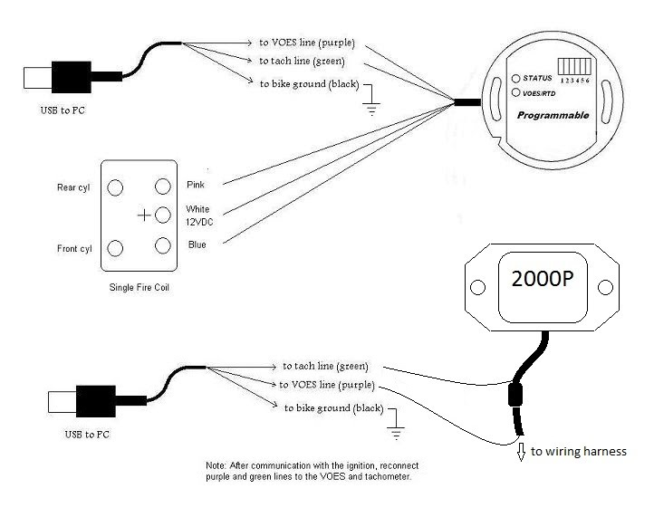
The black-and-white-striped wire from the harness goes to the negative terminal. The positive terminal receives the other white wire and a trace in black. The contact breaker is linked to the black wire. If you’re not sure about the connections between both, you can use a paper clip to remove them from the housing of the plug. Make sure that the terminals do not bend.
Accessory terminals
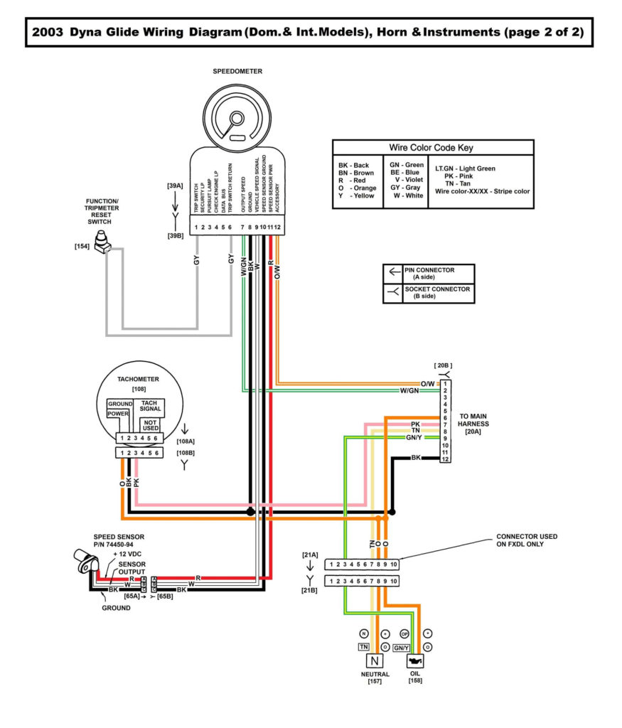
Diagrams of ignition wiring show the wires used to power the vehicle’s electrical supply. Typically there are four colored terminals for each part. Accessories are red and the battery yellow, the starter solenoid green. The “IGN terminal is used for starting the vehicle, controlling the wipers, and for other functions. The below diagram shows how to connect both the ACC terminal and ST terminals to the other components.
The terminal BAT holds the battery. The battery is essential for the electrical system to start. A dead battery can cause the switch to stop turning on. You can refer to your wiring diagram if you are uncertain about where the car’s batteries are. The accessory terminals in your car are connected to the ignition switch as well as the battery. The BAT terminal is connected to the battery.
Certain ignition switches have an additional position in which users can adjust their outputs as well as control them without having to turn on the ignition. In some cases, users may want to utilize the auxiliary output separately from the ignition. For the auxiliary output to be used, wire the connector with the same shade as that of the ignition. Then , connect it to the ACC end of the switch. While this is an excellent feature, there’s one crucial distinction. Most ignition switches are set up to display an ACC status when the car is in the ACC or START position.
Gallery of Dyna 2000 Ignition Wiring Diagram
Gallery of Dyna 2000 Ignition Wiring Diagram


