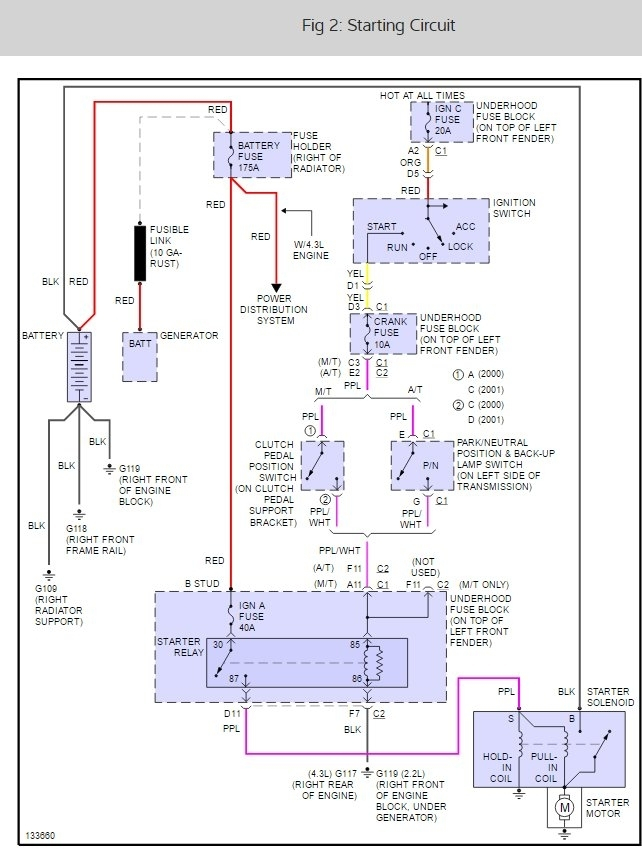
1997 S10 Ignition Switch Wiring Diagram – The first step is to look at the different terminals on the ignition switch. These are terminals for the Ignition, Coil, or Accessory. Once we’ve established the purpose of these terminals, we will be able to determine the various components of the ignition wiring. Then, we will discuss what functions are available for the Ignition switch and the Coil. After that, we will focus on the accessories terminals.
Terminals for ignition switch
An ignition switch is made up of three different switches. They are responsible for supplying the battery’s power to several places. The ON/OFF state of the switch that controls the ignition is managed by the first switch, which provides power to the choke when it’s pushed. Different manufacturers utilize their own color-coding method for the different conductors, which is documented in another article. OMC uses this system. The ignition switch comes with an adapter for the addition of an timer.
Although the majority of ignition switch terminals don’t appear in their original configuration however, the numbers may not be in line with the diagram. You should first check the integrity of the wires to ensure that they are connected to the correct ignition switch. A multimeter that is inexpensive can help you do this. Once you’ve verified the integrity of the wires you are able to connect the connector. If you have an ignition switch that is supplied by the manufacturer the wiring loom may be distinct from the one that is in your car.
In order to connect the ACC outputs to the auxiliary outputs on your vehicle, you have to first understand the way these two connections function. The ACC terminals and IGN terminals function as the standard connections for your ignition switch. The START and IGN connections are the primary connections for stereo and radio. The ignition switch controls the car’s engine. The terminals for the ignition switch on older cars are labeled with the alphabets “ACC” and “ST” (for individual magneto wires).
Terminals for coil
The terms used to define the type and model of an ignition coil is the most important thing. In a simple diagram of the wiring for ignition you’ll see a number of different connections and terminals, which include two primary and two secondary. Each coil has an operating voltage. The first step to determine which kind of coil you have is to check the voltage at S1 or the primary terminal. To determine whether it’s a Type A, C or B coil, you must also check the resistance of S1.
The chassis’ negative needs to be connected to the side of low-tension. This is the wiring diagram you will see on the diagram of wiring. The high-tension part supplies positive direct to the sparkplugs. The aluminum body of the coil has to be linked to the chassis for suppression but isn’t required. The diagram of the ignition wiring will also indicate the connection of the positive coil terminals. Sometimes, a damaged ignition coil is identified by a scan done at an auto parts shop.
The black-and-white-striped wire from the harness goes to the negative terminal. Positive terminal receives the white wire that includes a black trace. The black wire connects with the contact breaker. It is possible to remove the black wire from the housing of the plug with a paper clip If you’re unsure of the connections. You should also check to make sure that the connections are not bent.
Accessory terminals
Ignition wiring diagrams depict the various wires utilized to power various components. Typically there are four distinct colors-coded terminals that are used for each component. The accessories are red while the battery is yellow the starter solenoid green. The “IGN terminal” is used to run the wipers, and other operating functions. This diagram demonstrates how to connect ACC and ST terminals to the other components.
The terminal BAT connects the battery to the charger. Without the battery the electrical system can not start. The switch won’t be able to turn off if the battery isn’t there. If you don’t know the exact location where the battery in your car is situated, you can review your wiring diagram to figure out where it is. The accessory terminals of your vehicle are connected to the battery as well as the ignition switch. The BAT terminal is connected to the battery.
Some ignition switches feature a separate “accessory” location, which allows users can manage their outputs with no ignition. Some customers want the auxiliary output to be used independently from the ignition. In order for the auxiliary output be used, connect the connector to the same shade as the ignition. Then connect it with the ACC end of the switch. This is an excellent feature, but there is one important distinction. Most ignition switches are configured to be in an ACC position when the car is in the ACC position, whereas they’re set to the START position when the vehicle is in the IGN position.
Gallery of 1997 S10 Ignition Switch Wiring Diagram
Gallery of 1997 S10 Ignition Switch Wiring Diagram


