1986 Ford F150 Ignition Wiring Diagram – We will first examine the different types of terminals that are used on the ignition switch. These terminals comprise the Ignition switch, the Coil along with the Accessory. Once we have identified the terminals that are utilized and which ones are not, we can identify the different components of the 1986 Ford F150 Ignition Wiring Diagram. In addition, we will discuss the function of the Ignition switch and Coil. Following that, we will move on to the Accessory Terminals.
The terminals are for ignition switches.
An ignition switch contains three different switches that direct the battery’s current to different destinations. The ON/OFF state of the ignition switch is controlled by the second switch, which supplies power to the choke when it’s pulled. Different manufacturers use their own color-coding systems for the different conductors, that is described in a separate article. OMC uses the same method. An adapter is included on the ignition switch, allowing for the addition of a Tachometer.
While many ignition switch terminals could not be original, the numbering of each one might not be in line with the diagram. Before you plug in the ignition switch, be sure to test the continuity. You can do this with an inexpensive multimeter. After you have verified that the wires are in good condition, you can connect the connector. If your vehicle is equipped with an installed ignition switch the wiring diagram may differ.
Understanding how the ACC outputs are connected to the auxiliary outputs inside your vehicle is crucial. The ACC and IGN terminals are the default connections for your ignition switch. the START and IGN terminals are the principal connections for radio and stereo. The ignition switch’s function is to turn the car’s engines on and off. On older cars the ignition switch’s terminals are identified with the letters “ACC” as well as “ST” (for distinct magnet wires).
Terminals for coil
The terms used to define the model and type of an ignition coil is the primary thing. The basic ignition wiring diagram depicts various connections and terminals. There are two primary and one secondary. Each coil has an operating voltage. The first step to determine the kind you have is to check the voltage of S1 or the primary terminal. S1 should be tested for resistance in order to identify if the coil is Type A, B, and/or C.
The low-tension coil side must be connected to the chassis’ less. This is the wiring diagram you will see on the diagram of wiring. The high-tension part supplies the spark plugs with positive. For suppression purposes the coil’s body metal is required to be connected to the chassis. It is not required for electrical use. You will also see the connections between the positive and the negative coil’s terminals on the diagram of the ignition wiring. In certain cases scanning your local auto parts store will help identify defective ignition coils.
The black-and-white-striped wire from the harness goes to the negative terminal. Positive terminal gets the white wire that includes a black trace. The black wire connects to the contact breaker. To check the connections, use a paperclip or a pencil to lift them out of the housing for the plug. Make sure the terminals aren’t bent.
Accessory terminals
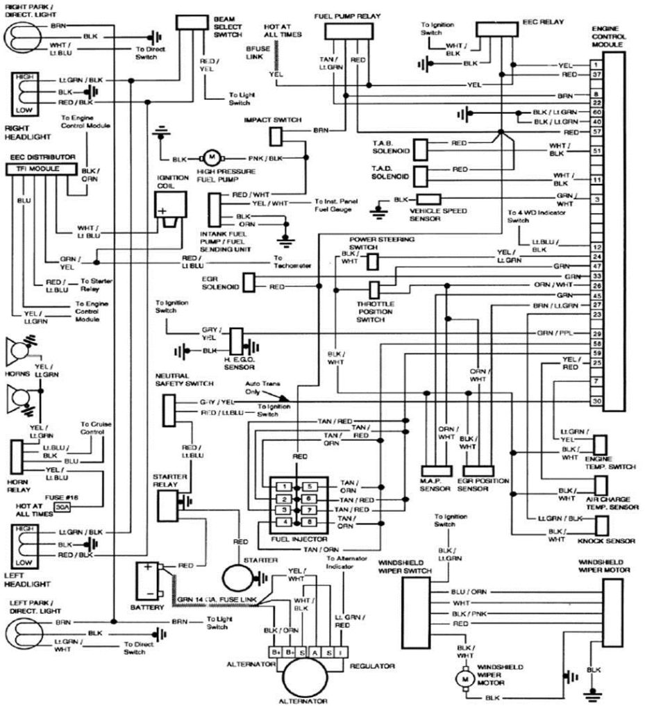
Diagrams of ignition wiring illustrate the wires that power various parts of the car. There are typically four different colors-coded terminus of each part. The red symbol represents accessories, yellow is for the battery, and green for the solenoid for starters. The “IGN terminal” is used to run the wipers, as well as other operating functions. The diagram shows how to connect the ACC and ST terminals to the rest of the components.
The battery is connected to the terminal named BAT. The electrical system won’t start in the event that the battery isn’t connected. The switch also won’t turn on without the battery. You can view the wiring diagram of your car to see where your car’s batteries are located. The ignition switch is connected to the car’s battery. The BAT terminal is connected with the battery.
Some ignition switches feature the “accessory” setting that permits users to control their outputs , without needing to turn on the ignition. Sometimes, users want to make use of an additional output independent of the ignition. In order to use the auxiliary output, wire the connector using the same colors as ignition connecting it to the ACC terminal on the switch. This is a convenient feature however it does have one significant differentiator. A lot of ignition switches can be programmed to have an ACC position when the vehicle has moved into the ACC position. They also will be in START mode after the vehicle has been entered the IGN position.
Gallery of 1986 Ford F150 Ignition Wiring Diagram
Gallery of 1986 Ford F150 Ignition Wiring Diagram


