4 Post Ignition Switch Wiring Diagram – The first step is to take a look at the different types of terminals used on the ignition switch. They include terminals that are used for Coil, Ignition Switch, and Accessory. Once we have established the purpose of these terminals are then we can identify the different parts of the 4 Post Ignition Switch Wiring Diagram. We’ll also go over what functions are available for the Ignition switch as well as the Coil. After that we will move on to the Accessory Terminals.
Terminals for ignition switches
The ignition switch has three switches. They feed the voltage of the battery to different places. The ON/OFF state of the ignition switch is controlled by the first switch, which provides power to the choke whenever it’s pushed. Different manufacturers utilize their own color-coding method for different conductors that is described in a separate article. OMC utilizes the same system. Connectors can be attached to the ignition switch in order to add an electronic tachometer.
While many ignition switch terminals do not appear in their original configuration The numbering might not match that of the diagram. Examine the continuity of the wires first to make sure they’re properly connected to the ignition switch. A multimeter is a good tool to test the continuity. When you’re happy with the quality of the connection then you can connect the new connector. The wiring loom in a factory-supplied ignition system switch is different.
Before you can connect the ACC outputs to the auxiliary outputs of your car it is crucial to know the fundamentals of these connections. The ACC terminals as well as the IGN terminals function as the standard connections for the ignition switch. The START and IGN connections are the most important connections for stereo and radio. The ignition switch is the one that turns the engine of your car on and off. Older vehicles have ignition switch terminals marked “ACC” or “ST” (for individual magnetowires).
Terminals for coil
To identify the kind of ignition coil, the first step is to know the terminology. In a simple ignition wiring diagram you’ll see a number of different terminals and connections, including two primary and two secondary. The operating voltage of each coil is different. This is why it is essential to first check the voltage at S1 (primary terminal). S1 should be examined for resistance to identify if the coil belongs to Type A, B, or C.
The chassis’ negative needs to be connected to the side of low-tension. This is also the ground on the ignition wiring diagram. The high-tension end supplies positive direct to the sparkplugs. It is necessary for suppression purposes that the metallic body of the coil is connected to the chassis, however it isn’t essential. The wiring diagram of the ignition will show you how to connect the terminals of either the negative or positive coils. Sometimes, an inspection at an auto part store can identify a problem with the ignition wire.
The black-and-white-striped wire from the harness goes to the negative terminal. The negative terminal is served by the black trace that’s joined to the white wire. The black wire connects to the contact breaker. If you’re unsure of the connections of the two, try using a paper clip to remove them from the housing of the plug. Also, make sure to ensure that the terminals haven’t been bent.
Accessory terminals
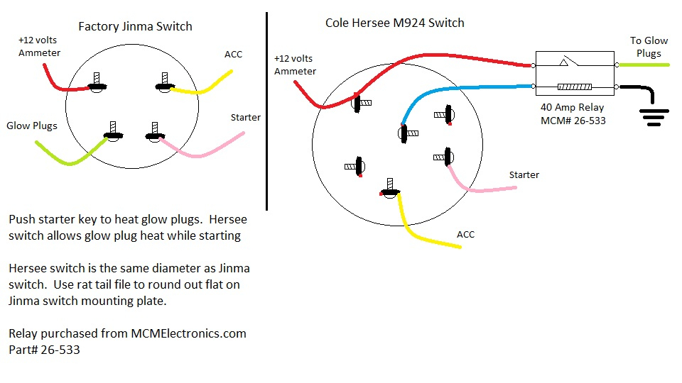
Diagrams of ignition wiring show the various wires utilized to power the vehicle’s various parts. There are usually four color-coded terminus for each component. The red color is for accessories, yellow to the battery and green is the starter solenoid. The “IGN” terminal is used to turn on the car, operate the wipers, as well as other functions. The diagram demonstrates how to connect the ACC and ST terminals to the other components.
The terminal BAT is the connection to the battery. The electrical system will not start in the event that the battery isn’t connected. A dead battery could make the switch stop turning on. If you’re not sure of where your car’s battery is located, you can review your wiring diagram to figure out how to locate it. The accessory terminals in your car connect to the ignition switch, as well as the battery. The BAT connector is connected to the battery.
Some ignition switches are equipped with an accessory position. This allows users to access their outputs from a different place without the ignition. Sometimes, customers want to make use of an additional output that is not connected to the ignition. You can utilize the auxiliary input by connecting the connector to the ACC terminal. Although this is a great option, there’s a thing you should know. Most ignition switches will be in an ACC position when the vehicle is in the ACC however they’ll be in the START position when the vehicle is IGN.
Gallery of 4 Post Ignition Switch Wiring Diagram
Gallery of 4 Post Ignition Switch Wiring Diagram


