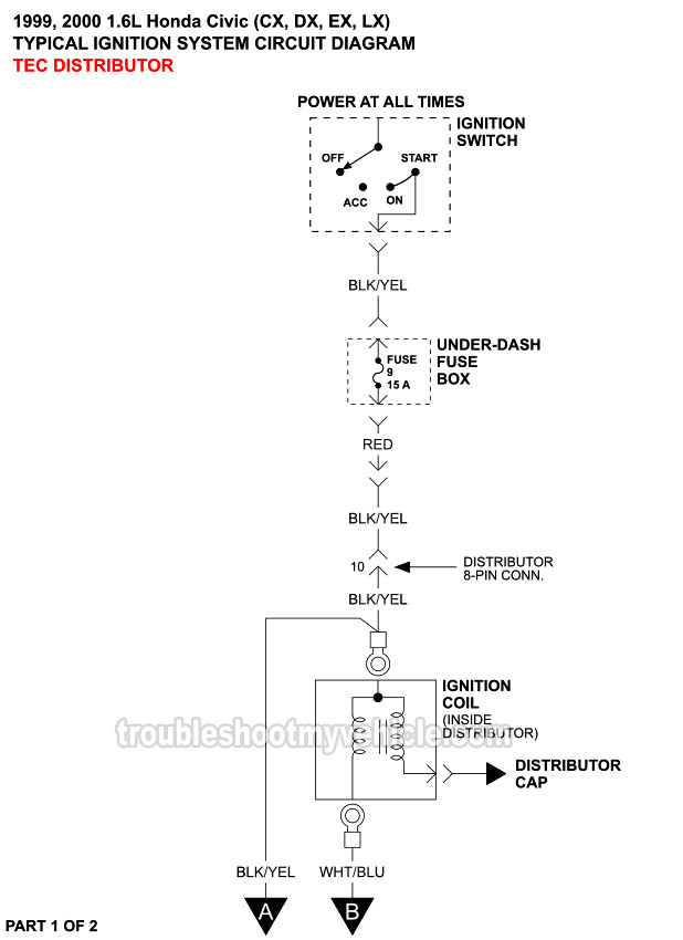
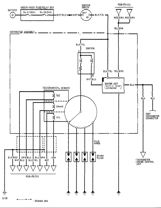
1999 Honda Civic Ignition Wiring Diagram – First, let’s look at the different terminals used on the ignition switch. These are terminals for Coil, Ignition Switch, and Accessory. Once we know what these types of terminals are, we will proceed to identify the different parts of the 1999 Honda Civic Ignition Wiring Diagram. In addition, we will discuss the different functions of the Ignition Switch and the Coil. After that, we will concentrate on the accessories terminals.
The terminals of the ignition switch
An ignition switch is composed of three different switches. They are responsible for supplying the battery’s power to various places. The ON/OFF position of the switch that controls the ignition is managed by the second switch, which delivers power to the choke when it’s pushed. Different manufacturers have different color-coding systems for different conductors. We’ll discuss this in a separate article. OMC follows this scheme. Connectors can be connected to the ignition switch to add the digital Tachometer.
While most ignition switch terminals may not be original, the numbering for each one may not be in line with the diagram. Examine the continuity of the wires first to ensure they’re properly connected to the ignition switch. This can be done with a multimeter that is inexpensive. Once you are satisfied that the wires are running in good harmony and you are able to connect the new connector. If you are using an ignition switch supplied by the manufacturer the wiring loom may be distinct from the one that is in your car.
The first step is to understand the distinctions between ACC and auxiliary outputs. The ACC terminals as well as the IGN terminals are the standard connections for your ignition switch. The START and IGN connections are the main connections for stereo and radio. The ignition switch switches the engine of your car ON and OFF. The terminals of older vehicles’ ignition switches are labeled with “ACC” as well as ST (for individual magneto wires).
Terminals for coil
The language used to decide the model and type of an ignition coil is the primary thing. An ignition wiring diagram will show a variety of terminals and connections, comprising two primary and two secondaries. Each coil operates at a specific voltage. The first step to determine which type you have is to check the voltage of S1 or the primary terminal. S1 must also be subjected to resistance tests to determine if it’s a Type A or B coil.
The chassis’ negative needs to be connected to the side of low-tension. This is the ground of the ignition wiring. The high-tension side delivers the positive power direct to the spark plugs. It is required for the purpose of suppression that the metallic body of the coil is connected to the chassis, but not essential. The wiring diagram for the ignition will explain how to connect the terminals of either the positive or negative coils. In certain instances you’ll discover that the ignition coil is damaged and is easily identified with scanning in an auto parts store.
The black-and-white-striped wire from the harness goes to the negative terminal. The other white wire is black-colored and connects to the negative terminal. The black wire connects with the contact breaker. If you’re not certain about the connections of both, you can use the clip of a paperclip to remove them from the housing of the plug. Be sure the terminals aren’t bent.
Accessory terminals
Ignition wiring diagrams show the various wires utilized to power the vehicle’s various parts. In general, there are four different colored terminals for each part. Accessories are red while the battery is yellow the starter solenoid is green. The “IGN terminal” is used to run the wipers, and other operating features. The diagram illustrates how you can connect ACC or ST terminals as well as the rest.
The terminal BAT connects the battery to the charger. The electrical system can’t begin without the battery. In addition the switch won’t come on. A wiring diagram can tell you where to find the battery of your car. The ignition switch is linked to the car’s battery. The BAT terminal is connected to the battery.
Some ignition switches come with an additional “accessory” position, where users can control their outputs with no ignition. Some customers prefer to use an auxiliary output that is not connected to the ignition. In order to use the auxiliary output, wire the connector using the same colors as the ignition, connecting it to the ACC terminal on the switch. This is a great option, but there’s an important distinction. Some ignition switches are configured to be in an ACC position once the car has been moved into the ACC position. They’ll also be in the START position after the vehicle has been moved into the IGN position.
Gallery of 1999 Honda Civic Ignition Wiring Diagram
Gallery of 1999 Honda Civic Ignition Wiring Diagram


