2002 Ford F250 Ignition Switch Wiring Diagram – Let’s first examine the various terminals on the ignition switch. These terminals comprise the Ignition switch, the Coil along with the Accessory. Once we know what these terminals are and what they do, we can then determine the various components in the ignition wiring. We’ll also discuss the roles of both the Ignition Switch and the Coil. Then, we’ll turn our attention to Accessory terminals.
The terminals are for ignition switches.
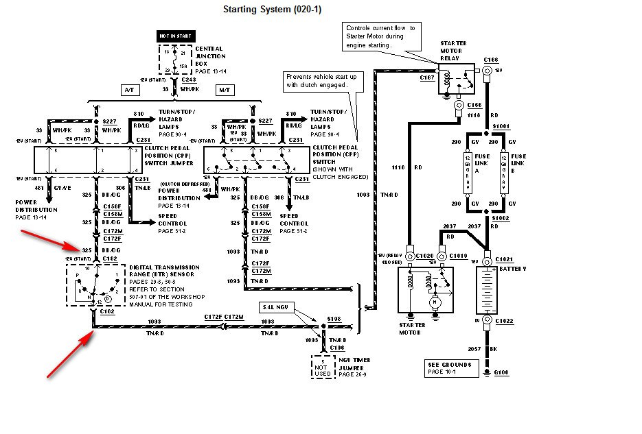
The ignition switch consists of three switches. They are responsible for supplying the battery’s power to several locations. The first switch supplies power to the choke whenever pushed, and the second is the ignition switch’s ON/OFF position. Different manufacturers have different color-coding systems for different conductors. We’ll discuss this in a separate article. OMC follows this system. A tachometer adapter is installed on the ignition switch to allow the addition of a tonometer.
While some ignition switch terminals do not have the original design however, the numbers may not match the diagram. To make sure that your wires are correctly connected to the switch it is recommended to check their continuity. A multimeter is a good instrument to verify the continuity. After you’re happy with the integrity of your wires, you’ll be able install the new connector. If your vehicle has an installed ignition switch, the wiring diagram will differ.
Before connecting the ACC outputs to the auxiliary outputs of your car, it is important to know the fundamentals of these connections. The ACC/IGN terminals function as the default connection on the ignition switch. The START/IGN terminals connect to the radio or stereo. The ignition switch is responsible for turning the car’s engine on and off. Older vehicles have ignition switch terminals labeled “ACC” or “ST” (for individual magnetowires).
Terminals for coil
To figure out the type of ignition coil, the first step is to know the terms. The basic ignition wiring diagram illustrates a variety of connections and terminals. There are two primary and one secondary. The coils come with a distinct operating voltage. The initial method of determining what type you have will involve testing the voltage on S1, the main terminal. S1 must also go through resistance testing to determine whether it’s a Type A or B coil.
The low-tension end of the coil needs to be connected to the chassis the negative. This is the base of the wiring for ignition. The high-tension side delivers positively directly to the spark plugs. For suppression purposes the coil’s metal body is required to be connected to the chassis. It is not required for electrical use. It is also possible to see the connections between the positive and the negative coil’s terminals on an ignition wiring diagram. Sometimes, an inspection at an auto part store can detect a defective ignition wire.
The black-and-white-striped wire from the harness goes to the negative terminal. The terminal that is negative is served by the trace in black that’s joined to the white wire. The black wire goes to the contact breaker. To test the connections between the two wires, use a paperclip and remove them off the housing. It is also important to make sure that the connections are not bent.
Accessory terminals

Diagrams of the ignition wiring depict the wires that supply power to different parts of the car. There are typically four colored terminals for each component. Red is used to indicate accessories, yellow to the battery and green for the starter solenoid. The “IGN” terminal can be used to start the car, operate the wipers, as well as other functions. The diagram shows how to connect ACC or ST terminals and the rest.
The battery is attached to the terminal whose name is BAT. Without the battery the electrical system can not begin. The switch won’t turn off if the battery isn’t there. To locate your car’s battery examine the wiring diagram. The accessory terminals of your car connect to the ignition switch, as well as the battery. The BAT terminal is connected to the battery.
Some ignition switches include an additional position in which users can modify their outputs as well as control them without having to turn on the ignition. In some cases, users may want to use the auxiliary input independently of the ignition. To allow the auxiliary output to be used, connect the connector to the same shade as the ignition. Then connect it with the ACC end of the switch. While this is an excellent feature, there’s one thing you should know. The majority of ignition switches are set to have an ACC position when the vehicle is in the ACC position, while they’re in the START position when the car is in the IGN position.
Gallery of 2002 Ford F250 Ignition Switch Wiring Diagram
Gallery of 2002 Ford F250 Ignition Switch Wiring Diagram


