1999 Toyota Camry Ignition Wiring Diagram – Let’s begin by looking at the different types of terminals in an ignition switch. These include terminals for Coil, Ignition Switch, and Accessory. After we’ve identified what these terminals do then we can be able to identify the various parts of the ignition wiring. We’ll also go over the functions of the Ignition switch and Coil. Then we’ll discuss the Accessory Terminals.
Terminals for ignition switch
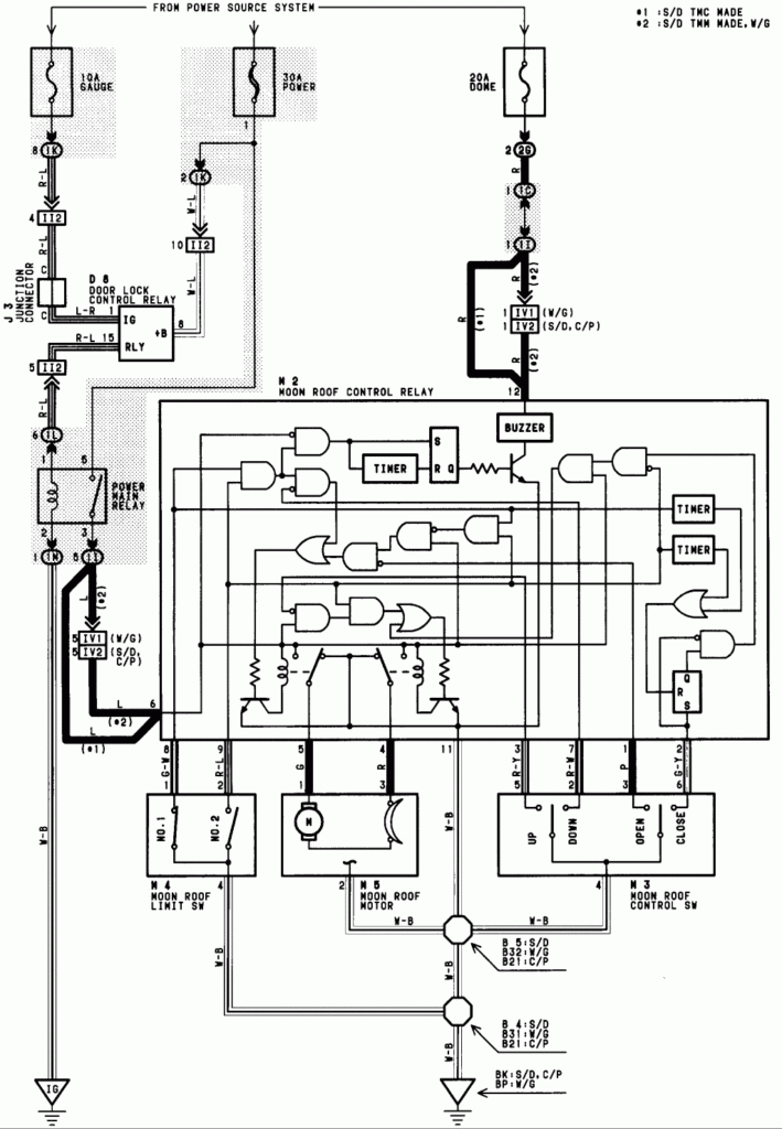
An ignition switch is made up of three switches. They are responsible for feeding the battery’s power to various locations. The first switch is the one that supplies the choke with power, and the third switch toggles the status of the ignition switch. Different manufacturers use different colors for different conductors. This is explained in a separate article. OMC follows this scheme. An adapter is included on the ignition switch to allow for the addition of the tachometer.
While many ignition switch terminals could not be authentic, the numbering of each one might not match the diagram. Check the continuity of all the wires to ensure they are correctly connected to the ignition switches. A multimeter is a great tool to test the continuity. When you’re satisfied that the wires are in good continuity and you are able to connect the new connector. If you’re using an ignition switch supplied by the manufacturer, the wiring loom is different from the one in your car.
First, understand the differences between the ACC and secondary outputs. The ACC and IGN terminals are the default connections for the ignition switch. the START and IGN terminals are the main connections for the stereo and radio. The ignition switch is the one that turns the engine of your car to and off. The ignition switch terminals on older cars are labeled with the initials “ACC” as well as “ST” (for each magneto wires).
Terminals for coil
Understanding the terminology is the first step towards determining which type of ignition coil you have. There are a variety of connections and terminals in a basic ignition wiring schematic which includes two primary as well as two secondary. The coils come with a distinct operating voltage, and the first step in determining which type you’re using is to test the voltage of S1 the main terminal. It is also recommended to check S1 for resistance in order to determine whether it is a Type A, B, or C coil.
The coil’s low-tension side should be connected at the chassis’s less. This is what is known as the ground for the wiring for ignition. The high-tension component provides the spark plugs with positive. To prevent noise the body of the coil is required to be connected to the chassis. But, it’s not required to connect electrically. The ignition wiring diagram will also outline how to connect the positive coil’s terminals. You may find an ignition coil problem which can be identified by scanning it in the auto parts shop.
The black-and-white-striped wire from the harness goes to the negative terminal. The terminal for the negative is served by the trace in black that’s attached to the white wire. The black wire is connected to the contactbreaker. To verify the connections, make use of a paperclip or pencil to lift them out of the plug housing. You should also check to ensure that the terminals aren’t bent.
Accessory terminals
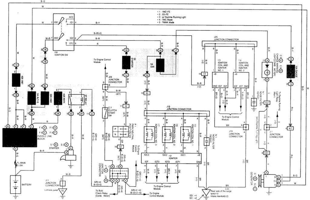
Diagrams of ignition wiring show the wires used in the vehicle’s power supply. There are usually four colored terminals that correspond to each component. For accessories, red stands for starter solenoid, yellow is for battery, and blue for accessories. The “IGN terminal” is used to provide power to the wipers as well as other operating features. The diagram below shows how to connect both the ACC terminal and ST terminals to various components.
The battery is connected to the terminal called BAT. The battery is necessary to allow the electrical system to get started. Additionally the switch isn’t turned on. A wiring diagram can inform the location of the battery of your car. The accessory terminals of your car are connected to the ignition switch, as well as the battery. The BAT Terminal is connected to the Battery.
Some ignition switches offer the option of an “accessory position” which allows users to alter their outputs without the ignition. Users may wish to use the auxiliary output separately from the ignition. Make use of the additional output by connecting it to the ACC terminal on your switch using the same colors. Although this is a useful feature, there is one significant difference. Most ignition switches come with an ACC position when your car is in the ACC mode and a START mode when you are in IGN.
Gallery of 1999 Toyota Camry Ignition Wiring Diagram

Gallery of 1999 Toyota Camry Ignition Wiring Diagram


