Inboard Boat Ignition Switch Wiring Diagram – Let’s begin by examining the different types and functions of the terminals that are found in the ignition switches. These terminals comprise the Ignition switch as well as the Coil and the Accessory. After we’ve identified the purpose of the terminals it is possible to determine the various components of the ignition wiring. We will also talk about the functions and the Coil. The next step is to focus on the accessory terminals.
Terminals for ignition switches
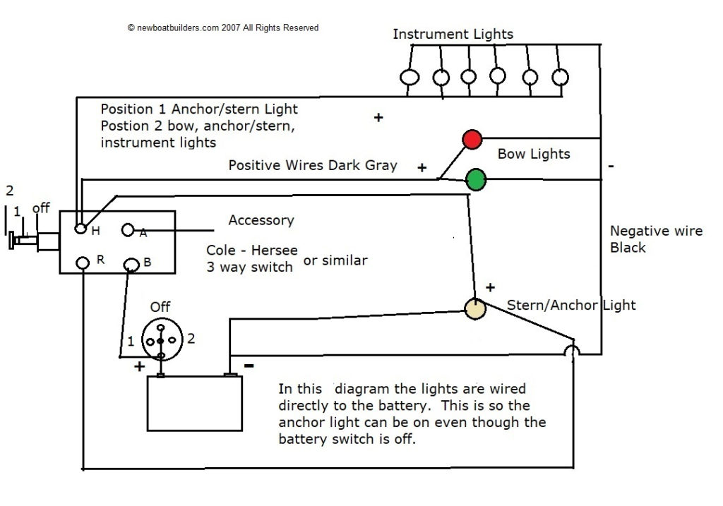
The ignition switch has three switches. They feed the voltage of the battery to different locations. The first switch is the one that supplies power to the choke, and the third switch toggles the status of the ignition switch. Different manufacturers employ different color codes for various conductors. This is described in a different article. OMC utilizes this system. The ignition switch is also equipped with a connector for adding the tachometer.
While many ignition switch terminals do not come in original form The numbering might not match the diagram. Check the electrical continuity first to ensure that they’re properly connected to the ignition switch. A multimeter is a great instrument to verify the continuity. Once you are satisfied that the wires are in good order then you can connect the new connector. If your vehicle is equipped with an ignition switch that is installed the wiring diagram may differ.
The first step is to understand the distinctions between the ACC and the auxiliary outputs. The ACC terminals as well as the IGN terminals are the primary connections to the ignition switch. The START and IGN connections are the primary connections for stereo and radio. The ignition switch is the one that controls the engine of your car. The terminals of the ignition switch on older vehicles are marked with the initials “ACC” as well as “ST” (for the individual magneto wires).
Terminals for coil
Understanding the terminology utilized is the initial step in determining what type of ignition coil. A simple diagram of the wiring will display a range of terminals and connections comprising two primary and two secondaries. The coils are equipped with a particular operating voltage, and the first step in determining which type you’ve got is to check the voltage at S1, the primary terminal. S1 must be tested for resistance in order to determine if the coil belongs to Type A, B, or C.
The coil’s low-tension end is to be connected to the chassis’ positive. This is also the ground on the diagram of the ignition wiring. The high-tension component supplies the positive power directly to the spark plugs. The metal body of the coil needs to be connected to the chassis to prevent it from being smothered but is not electrically essential. The wiring diagram will depict the connection between positive and negative coil terminals. Sometimes, an inspection at an auto parts store could diagnose a malfunctioning ignition wire.
The black-and-white-striped wire from the harness goes to the negative terminal. The white wire also is black with a trace on it and it goes to the positive terminal. The contact breaker is attached to the black wire. To verify the connections, you can make use of a paperclip or pencil to remove them from the plug housing. It’s also essential to make sure that the terminals don’t bend.
Accessory terminals
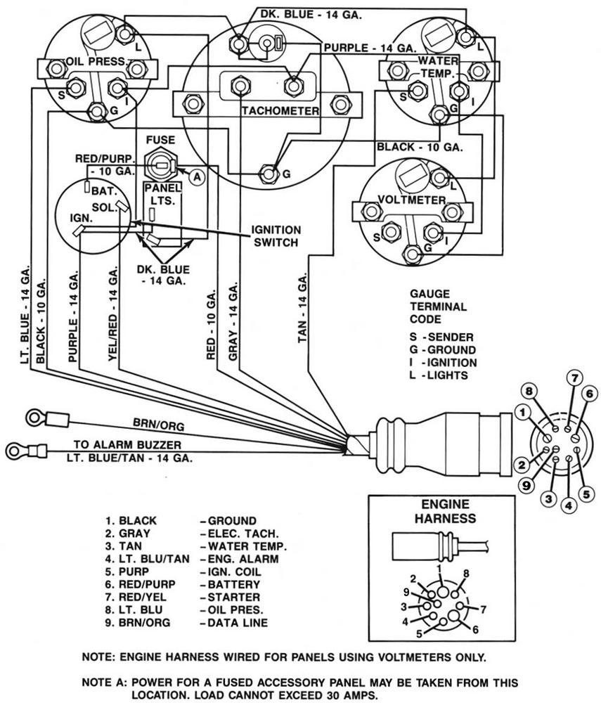
Diagrams of ignition wiring show the wiring used to provide power to various components of the vehicle. There are generally four colored terminals for each component. The red symbol represents accessories, yellow is for the battery and green for the starter solenoid. The “IGN terminal” is used to power the wipers along with other operational features. The diagram illustrates how you can connect ACC or ST terminals as well as the rest.
The battery is connected to the terminal whose name is BAT. The battery is essential to allow the electrical system to start. Additionally, the switch won’t start. You can refer to your wiring diagram if not sure where the batteries of your car are. The accessory terminals of your car are connected to the battery as well as the ignition button. The BAT connector is connected to the battery.
Certain ignition switches have a separate “accessory” location, which allows users can manage their outputs with no ignition. Sometimes, customers would like the auxiliary output to be operated independently of the ignition. In order to use the auxiliary output, connect the connector using the same colors as ignition connecting it to the ACC terminal on the switch. This is a great feature, however there’s an important distinction. Many ignition switches have an ACC position when your vehicle is in ACC mode, and a START position when it is in IGN.
Gallery of Inboard Boat Ignition Switch Wiring Diagram
Gallery of Inboard Boat Ignition Switch Wiring Diagram


