2000 Blazer Ignition Switch Wiring Diagram – First, let’s examine the various terminals that are used in the ignition switch. These include the terminals for the Ignition switch, Coil, and Accessory. When we have a clear understanding of the purpose of each terminal, we are able to determine the components of the ignition wiring. We’ll also discuss the functions as well as the Coil. Then, we’ll talk about the function of the ignition switch and Coil.
Terminals for the ignition switch
An ignition switch contains three separate switches that feed the battery’s current to different locations. The first one is used to turn on the choke through pushing it, and the third switch is used to control the ON/OFF position. Every manufacturer has its individual color-coding system that we’ll go over in a separate article. OMC uses this method. Connectors can be connected to the ignition switch in order to include a digital tachometer.
While most ignition switch terminals are duplicated, the number may not be consistent with the diagram. Check the continuity of the wires first to ensure they’re connected correctly to the ignition switch. A cheap multimeter can assist you in this. After you’ve confirmed the integrity of the wires you can then connect the connector. If you’re using an ignition switch supplied by the manufacturer the wiring loom may be different from the one you have in your car.
Before you can connect the ACC outputs to the auxiliary outputs of your car, it is important to know the fundamentals of these connections. The ACC and IGN connectors are the default connections for your ignition switch. Although the START, IGN, and ACC terminals are the main connections for radios or stereo, the START/IGN connections are the most important ones. The ignition switch’s function is for turning the car’s engine on and off. Older vehicles are identified with the alphabets “ACC”, “ST”, (for individual magneto cables) on their ignition switch’s terminals.
Terminals for coil
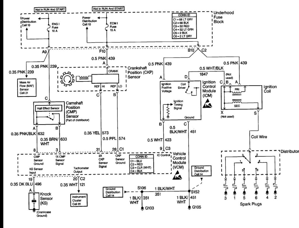
The first step in determining the type of ignition coil is to understand the terms that is used. You will see several connections and terminals within the basic wiring diagram for ignition, including two primary, and two secondary. The operating voltage of each coil differs. This is why it is crucial to test the voltage at the S1 (primary terminal). You should also examine S1 for resistance to identify if it’s a Type A or B coil.
The lower-tension side of the coil must be connected to the chassis the negative. This is also the ground in the ignition wiring diagram. The high-tension supply provides positively directly to spark plugs. For suppression purposes the coil’s metal body is required to be connected to the chassis. It’s not necessary to use electricity. It is also possible to see the connections between the positive and negative coil terminals on the ignition wiring diagram. In some cases, a scan at the local auto parts store will be able to diagnose malfunctioning ignition coils.
The black-and-white-striped wire from the harness goes to the negative terminal. The white wire also has a black trace, and it connects to the positive terminal. The black wire connects to the contact breaker. To check the connection, employ a paperclip, or a pencil to lift them out from the plug housing. It’s also essential to make sure the terminals aren’t bent.
Accessory terminals
The wiring diagrams for the ignition show the various wires that provide power to the various parts of the car. In general there are four color-coded terminals for each component. For accessories, red stands the starter solenoid’s color, yellow for battery and blue for accessory. The “IGN terminal is used for starting the vehicle, controlling the wipers and other functions. The diagram shows the connection of the ACCas well as ST terminals.
The terminal BAT connects the battery to the charger. The electrical system will not start when the battery isn’t connected. Additionally the switch isn’t turned on. You can refer to your wiring diagram if uncertain about where the car’s batteries are. The accessory terminals of your car are connected to the ignition switch as well as the battery. The BAT terminal is connected to the battery.
Certain ignition switches have an additional “accessory” location, which allows users can control their outputs with no ignition. Sometimes, customers want to use an auxiliary output that is not connected to the ignition. In order to use the auxiliary output, connect the connector in the same colors as the ignition, and connect it to the ACC terminal on the switch. This option is useful, but it has one key distinction. Most ignition switches will have an ACC position when the vehicle is in the ACC however, they’ll be at the START position if the vehicle is IGN.
Gallery of 2000 Blazer Ignition Switch Wiring Diagram
Gallery of 2000 Blazer Ignition Switch Wiring Diagram


