Thunderheart Ignition Wiring Diagram – We will first look at the various kinds and functions of terminals found in the ignition switches. These are the terminals that connect the Ignition, Coil, or Accessory. After we’ve identified what these terminals do, we will determine the various components in the ignition wiring. We will also talk about the functions and the Coil. After that, we’ll turn our attention to the Accessory terminals.
Terminals for the ignition switch
An ignition switch has three switches. They transmit the battery’s voltage to different places. The first switch provides power to the choke when it is pushed. The second is the switch that controls the ignition’s ON/OFF positions. Every manufacturer has its individual color-coding system that we’ll go over in a separate article. OMC follows this scheme. A connector can be added to the ignition switch in order to include the digital tachometer.
While many ignition switch terminals could not be original, the numbers of the terminals may not be in line with the diagram. Before you plug into the ignition switch ensure that you check the continuity. This can be done with an inexpensive multimeter. After you’re happy with the integrity of your wires, you will be able install the new connector. The wiring loom for an ignition switch that’s factory-supplied will be different than the one you have in your car.
In order to connect the ACC outputs to the auxiliary outputs of your vehicle, you have first know the way these two connections function. The ACC/IGN connections function as the default connections on the ignition switch. The START/IGN terminals connect to the radio or stereo. The ignition switch’s function is for turning the car’s engine on and off. The terminals of older cars ignition switches are marked by “ACC” as well as ST (for individual magneto wires).
Terminals for coil
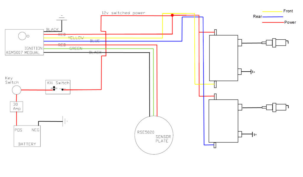
The terminology used to determine the kind and model of an ignition coil is the most important thing. An ignition wiring diagram will display a range of terminals and connections, comprising two primary and two secondary. Each coil is operating at a certain voltage. The first step in determining which type you’re dealing with is to test the voltage of S1 or the primary terminal. To determine whether it’s a Type A, C or B coil, you must also check the resistance of S1.
The coil’s low-tension end must be connected with the chassis’ positive. This is what is known as the ground for the ignition wiring. The high-tension side supplies positive direct to the spark plugs. The aluminum body of the coil has to be linked to the chassis to prevent it from being smothered but isn’t required. The wiring diagram will also show the connection between the positive and negative coils. Sometimes, a visit to an auto parts shop can detect a defective ignition wire.
The black-and-white-striped wire from the harness goes to the negative terminal. The positive terminal receives the white wire and the black trace. The contact breaker is linked to the black wire. It is possible to check the connections using a paperclip to remove the wires of the housing. Be sure to check that the terminals aren’t bent.
Accessory terminals
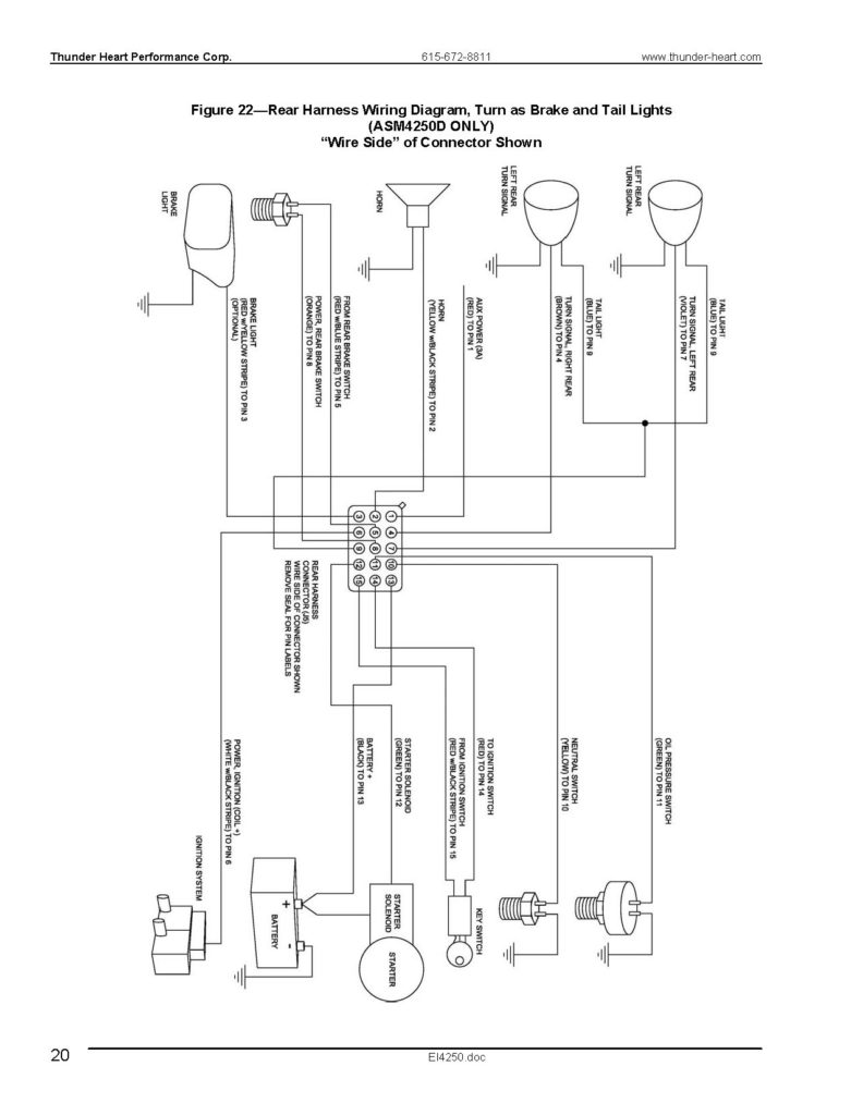
Ignition wiring diagrams show the different wires that are utilized to power the vehicle’s various components. There are generally four color-coded terminals to each component. The red symbol represents accessories, yellow is for the battery and green is for the solenoid for starters. The “IGN” terminal is used to start the car , and also to operate the wipers as well as other operational functions. The diagram illustrates the connection between the ACC- and ST terminals.
The terminal BAT is the connection to the battery. The electrical system can’t start without the battery. The switch won’t turn off if the battery isn’t there. The wiring diagram will inform the location of the battery of your car. The ignition switch is connected to the battery of your car. The BAT connector is connected to the battery.
Certain ignition switches have an additional position. It allows users to connect their outputs to another location without the ignition. Some customers prefer to use an auxiliary output that is not connected to the ignition. The auxiliary output could be connected by wiring the connector with the same color as your ignition and connecting it to the ACC terminal of the switch. This convenience feature is great, but there is one difference. Most ignition switches are set up to show an ACC status when the vehicle is in the ACC or START position.
Gallery of Thunderheart Ignition Wiring Diagram
Gallery of Thunderheart Ignition Wiring Diagram


