Honda Recon Ignition Switch Wiring Diagram – Let’s begin by looking at the different types terminals found on an ignition switch. The terminals are the Ignition switch as well as the Coil along with the Accessory. Once we understand the function of each type of terminal, it is possible to identify the various components of the ignition wiring. We’ll also be discussing the functions of the Ignition switch, as well as the Coil. We’ll then turn our attention on the accessory terminals.
Terminals for ignition switch
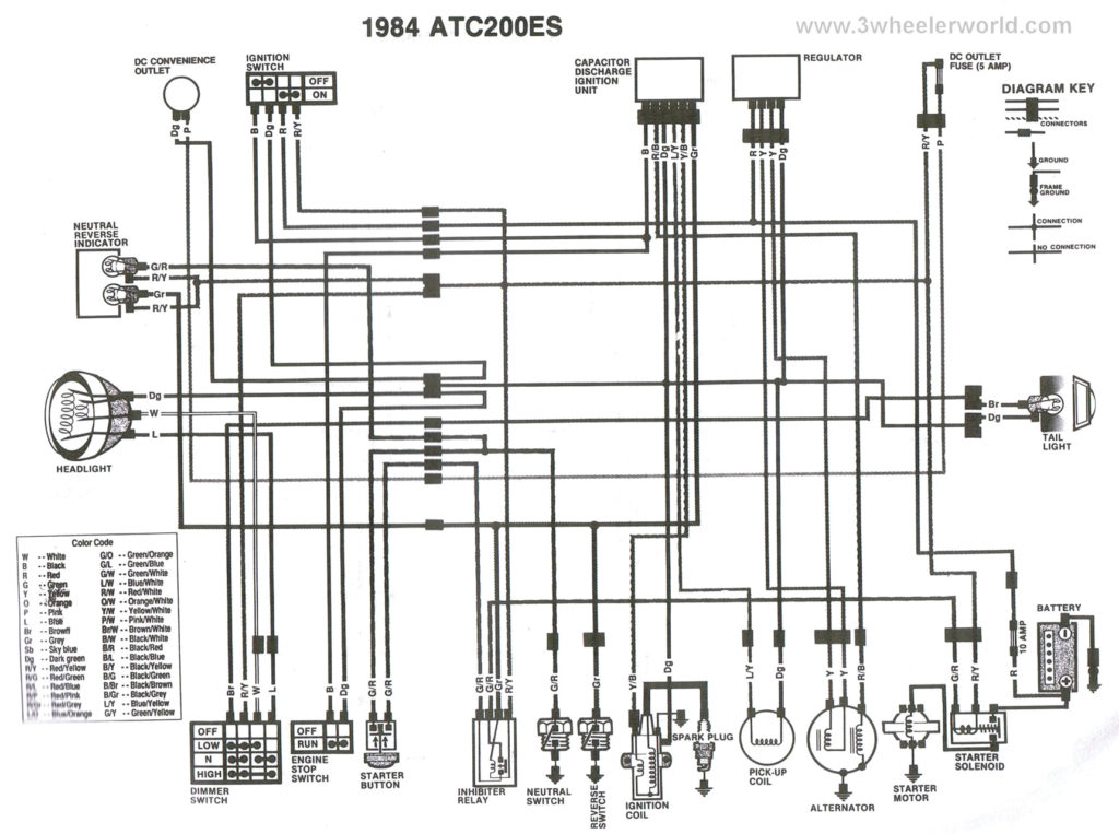
The ignition switch has three switches. They transmit the battery’s voltage to different locations. The first switch powers the choke. The third switch regulates the ON/OFF function of the ignition switch. Every manufacturer has its individual color-coding system that we’ll go over in a separate article. OMC follows this system. The connector allows for the connection of a speedometer to the ignition switch.
Although the majority of ignition switch terminals don’t have an initial number, they could have a different number. Check the integrity of the wires to ensure that they are connected to the correct ignition switch. This can be accomplished using a simple multimeter. When you’re satisfied with the continuity of the wires, then you’ll be able to connect the new connector. The wiring loom of an ignition switch that’s supplied by the factory will be different from the one that you have in your vehicle.
Knowing how the ACC outputs connect to the other outputs of your car is vital. The ACC and IGN terminals are the default connections on your ignition switch, and the START and IGN terminals are the primary connections for radio and stereo. The ignition switch switches the engine of your car ON and OFF. Older cars have the ignition switch’s terminals that are labeled “ACC” or “ST” (for individual magnetowires).
Terminals for coil
Understanding the terminology used is the initial step to determining what kind of ignition coil to choose. You will see several connections and terminals on an ignition wiring schematic, including two primary, and two secondary. It is essential to identify the type of coil you have by testing the voltage at the primary terminal S1. S1 should also be checked for resistance in order to identify if it’s a Type B, B or A coil.
The negative end of the chassis must be connected to the coil’s low-tension side. This is the ground on the diagram of ignition wiring. The high tension side supplies positively directly to the spark plugs. It is necessary to suppress the coil’s metallic body be connected to the chassis, however, it is not necessary. It is also possible to see the connections of the positive and negative coil terminals on the ignition wiring diagram. There could be an issue with the ignition coil which can be identified by scanning it in the auto parts shop.
The black-and-white-striped wire from the harness goes to the negative terminal. The white wire is black-colored and connects to the terminal opposite. The black wire goes to the contact breaker. To test the connections between the two wires, employ a paperclip to lift them out of the housing. Also, make sure to ensure that the terminals have not been bent.
Accessory terminals
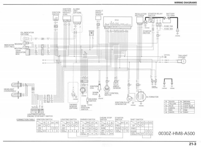
Ignition wiring diagrams depict the different wires used for powering the various components. Each component has four distinct connections that are color coded. Red refers to accessories, yellow to the battery, and green is the starter solenoid. The “IGN” terminal can be used to start the car, operate the wipers, as well as other features. This diagram shows how you can connect ACC and ST terminals to the rest of components.
The terminal BAT is the connector for the battery. The battery is necessary to allow the electrical system to begin. Furthermore, the switch won’t start. It is possible to refer to your wiring diagram if not sure where the batteries of your car are located. The accessory terminals in your car are connected to the ignition switch, as well as the battery. The BAT connector is connected to the battery.
Certain ignition switches have an accessory position. This allows users to connect their outputs to another location without the ignition. Users may wish to utilize the auxiliary output separately from the ignition. You can utilize the secondary input by connecting it to the ACC terminal. Although this is a fantastic feature, there’s something to be aware of. The majority of ignition switches are set to have an ACC position when the car is in the ACC position, while they’re in the START position when the vehicle is in the IGN position.
Gallery of Honda Recon Ignition Switch Wiring Diagram
Gallery of Honda Recon Ignition Switch Wiring Diagram


