2000 Honda Civic Ignition Switch Wiring Diagram – Let’s begin by examining the different types and purposes of the terminals that are found on the ignition switches. They are the terminals used that are used for Coil, Ignition Switch, and Accessory. Once we know the purpose of each kind of terminal, we can then determine the components of the ignition wiring. In addition, we will discuss the roles of the Ignition switch and Coil. Following that, we will discuss the Accessory Terminals.
The terminals of the ignition switch
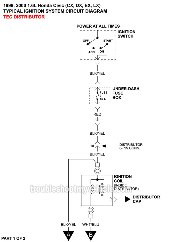
The ignition switch has three switches. They feed the battery’s voltage to many different places. The first is utilized to turn on the choke by pushing it. Then, the second is for the ON/OFF position. Each manufacturer has their own color-coding system, which we will discuss in another article. OMC utilizes this method. There is a connector inside the ignition switch to allow connecting an to a tachometer.
Although many ignition switch terminals don’t appear in their original configuration, the numbering may not be in line with the diagram. Check the continuity of the wires to see if they are plugged into the correct ignition switch. A multimeter is a good instrument to verify the continuity. When you’re satisfied that the wires are in good order then you can connect the new connector. If you are using an ignition switch that is supplied by the manufacturer the wiring loom will be different from that used in your vehicle.
Understanding how the ACC outputs connect to the other outputs of your vehicle is crucial. The ACC, IGN and START terminals are the primary connection to the ignition switch. They also serve as the primary connections to the radio and stereo. The ignition switch acts as the engine’s switch to turn off or on. Older vehicles are identified with the initials “ACC”, “ST”, (for individual magneto cables) at their ignition switch terminals.
Terminals for coil
The first step in determining the kind of ignition coil is to understand the terminology that is used. In a simple ignition wiring diagram, you will see a number of different connections and terminals, such as two primary and two secondary. The operating voltage of each coil is different. This is why it is crucial to test the voltage at S1 (primary terminal). To determine if it is a Type A, C or B coil, you should also test the resistance on S1’s.
The coil with low tension must be connected at the chassis’s minus. This is also the ground on the ignition wiring diagram. The high-tension side supplies positive direct to the sparkplugs. The coil’s metal body needs to connect to the chassis to prevent it from being smothered, but it is not electrically necessary. The ignition wiring diagram will also reveal the connection of the negative and positive coil’s terminals. In some cases, you’ll find that the ignition coil is damaged and can be diagnosed with scanning at an auto parts shop.
The black-and-white-striped wire from the harness goes to the negative terminal. The positive terminal also gets the white wire that is black in its trace. The contact breaker is attached to the black wire. To test the connections between the two wires employ a paperclip to remove them off the housing. Be sure to verify that the connections haven’t been bent.
Accessory Terminals
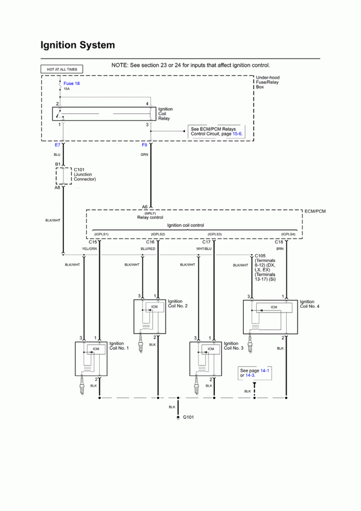
Ignition wiring diagrams depict the various wires utilized to power various components. There are generally four terminals with color codes that are connected to the component. Red is used for accessories, yellow is for the battery, while green is for the starter solenoid. The “IGN” terminal is used to start the car , and also to operate the wipers, as well as other operating functions. The diagram shows how to connect the ACC and ST terminals to the other components.
The terminal BAT connects the battery to the charger. The electrical system is not able to start without the battery. Additionally, the switch won’t start. It is possible to view your wiring diagram to figure out where the batteries of your car are placed. The ignition switch is connected to the car’s battery. The BAT Terminal is connected to the battery.
Some ignition switches offer the option of an “accessory position” that allows users to modify their outputs independent of the ignition. In some cases, users may want to utilize the auxiliary input independently of the ignition. For the auxiliary output to be used, plug in the connector with the same shade as the ignition. Connect it to the ACC end of the switch. Although this is a great feature, there’s something you should know. Most ignition switches will be in an ACC position when the vehicle is in ACC however they’ll be at the START position when the vehicle is in IGN.
Gallery of 2000 Honda Civic Ignition Switch Wiring Diagram
Gallery of 2000 Honda Civic Ignition Switch Wiring Diagram


