Cole Hersee Ignition Switch 95060 Wiring Diagram – We’ll begin by looking at different kinds of terminals that are found on an ignition switch. These terminals are for the Ignition button, Coil and Accessory. Once we know the terminals used then we can identify the different components of the Cole Hersee Ignition Switch 95060 Wiring Diagram. We’ll also discuss the functions and the Coil. Then we’ll discuss the Accessory Terminals.
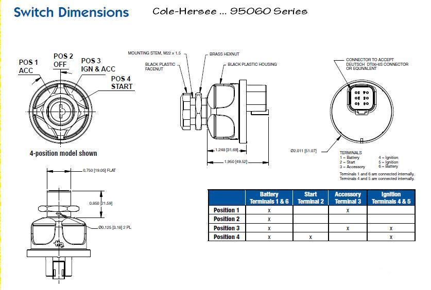
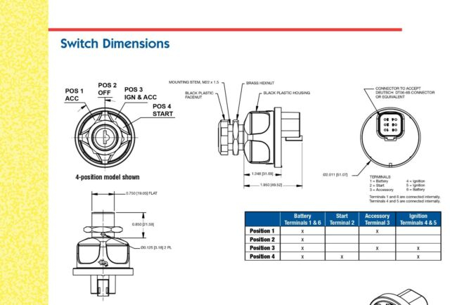
Ignition switch terminals
An ignition switch is comprised of three switches. They supply the battery’s voltage to many different places. The first is utilized to turn on the choke by pushing it, while another switch controls the ON/OFF setting. Every manufacturer has its unique color-coding system, which we will discuss in another article. OMC utilizes this method. The adapter is attached to the ignition switch that allows the installation of the tachometer.
While many ignition switch terminals may not be authentic, the numbering of the terminals may not be in line with the diagram. You should first check the continuity of the wires to determine if they’re connected to the ignition switch in the correct way. This can be checked using a simple multimeter. When you’re satisfied that all wires are in good order, you can attach the new connector. The wiring loom used in a factory-supplied ignition system switch is different.
For connecting the ACC outputs to the auxiliary outputs on your car, you’ll need to understand how these two connections work. The ACC terminals and IGN terminals are the primary connections to the ignition switch. The START and IGN connections are the most important connections for radio and stereo. The ignition switch turns the engine of your car ON and off. Older cars are equipped with ignition switch’s terminals that are labeled “ACC” or “ST” (for individual magnetowires).
Terminals for coil
The language used to decide the model and type of the ignition coil is the primary thing. In a typical ignition wiring diagram, you will see various terminals and connections, including two primary and two secondary. Each coil has a specific operating voltage. To determine the type of coil you have first, you need to test the voltage at S1, the primary terminal. S1 should also be tested for resistance to determine whether it’s an A, Type B or A coil.
The chassis’ negative must be connected to connect the coil’s low-tension side. This is the base of the wiring for ignition. The high-tension part connects the spark plugs to a positive. To reduce the noise the coil’s body metal must be connected to the chassis. It’s not necessary for electrical use. There are also connections of the positive and negative coil terminals on the diagram of the ignition wiring. Sometimes, a damaged ignition coil can be identified with a scan in an auto parts shop.
The black-and-white-striped wire from the harness goes to the negative terminal. The positive terminal also receives a white wire that has a black trace. The black wire connects to the contactbreaker. To verify the connection, employ a paperclip, or a pencil to pull them out of the housing for the plug. Make sure that the connectors don’t bend.
Accessory terminals
The ignition wiring diagrams illustrate the different wires used to power the various components of the vehicle. Typically there are four distinct color-coded terminals for each component. To identify accessories, red is for starter solenoid, blue for battery and blue for accessories. The “IGN” terminal is used for starting the car, controlling the wipers and various other functions. The diagram illustrates how you can connect ACC or ST terminals, and other.
The terminal BAT is the connection for the battery. The electrical system can’t be started without the battery. Additionally, the switch won’t begin to turn on. To locate your car’s battery look over your wiring diagram. The ignition switch and battery are connected via accessory terminals. The BAT Terminal is connected to the Battery.
Some ignition switches include an accessory position where users can adjust their outputs as well as control them without having to turn on the ignition. Sometimes, a customer wants to make use of the auxiliary output separately from the ignition. It is possible to use the additional input by connecting it to the ACC terminal. This is a great feature, but there is an important difference. The majority of ignition switches are set to have an ACC position when the vehicle is in the ACC position, but they’re set to the START position when the vehicle is in the IGN position.
Gallery of Cole Hersee Ignition Switch 95060 Wiring Diagram
Gallery of Cole Hersee Ignition Switch 95060 Wiring Diagram


